Method and device for capturing charged molecules traveling in a flow stream

a flow stream and charged molecule technology, applied in the direction of isotope separation, diaphragm, electrolysis, etc., can solve the problem of local electric field strength differences and achieve the effect of simple construction

Active Publication Date: 2005-12-29
PERKINELMER U S LLC +2
View PDF1 Cites 42 Cited by
  • Summary
  • Abstract
  • Description
  • Claims
  • Application Information

AI Technical Summary

Problems solved by technology

In this case, the physico-chemical properties of the electrophoresis buffer are interrupted, resulting in local differences in the electric field strength in which ions move with different velocities toward the electrodes.

Method used


Image

  • Method and device for capturing charged molecules traveling in a flow stream
  • Method and device for capturing charged molecules traveling in a flow stream
  • Method and device for capturing charged molecules traveling in a flow stream

Examples


example 1

Experimental Evidence for the Membrane-Based Stacking Principle

[0119] In order to validate the theoretical principle, a device that contains all desirable characteristics outlined in the theoretical part was built and tested.

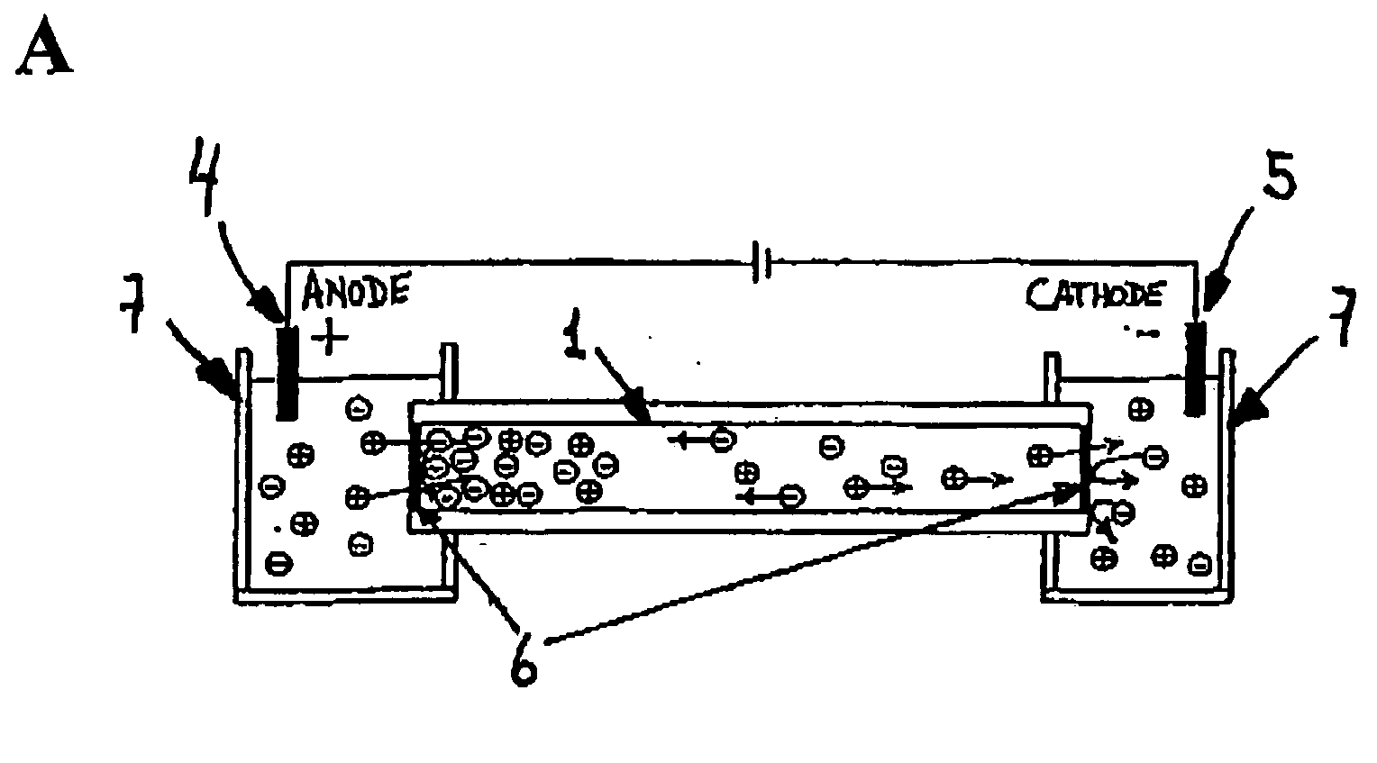
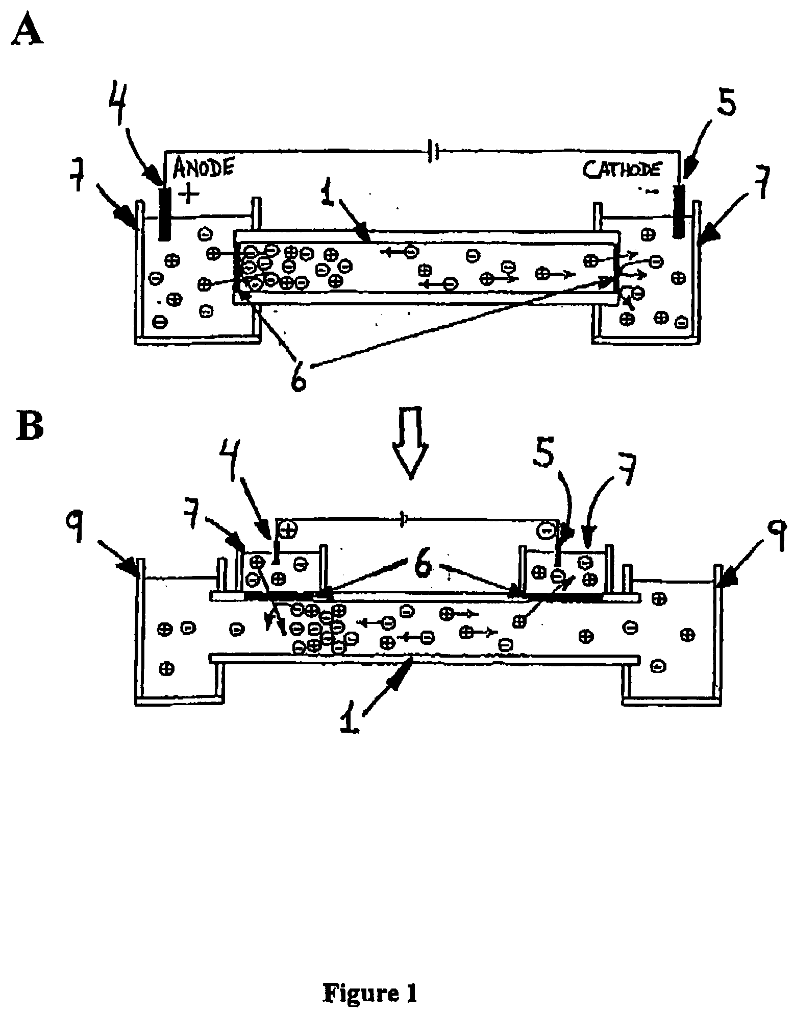
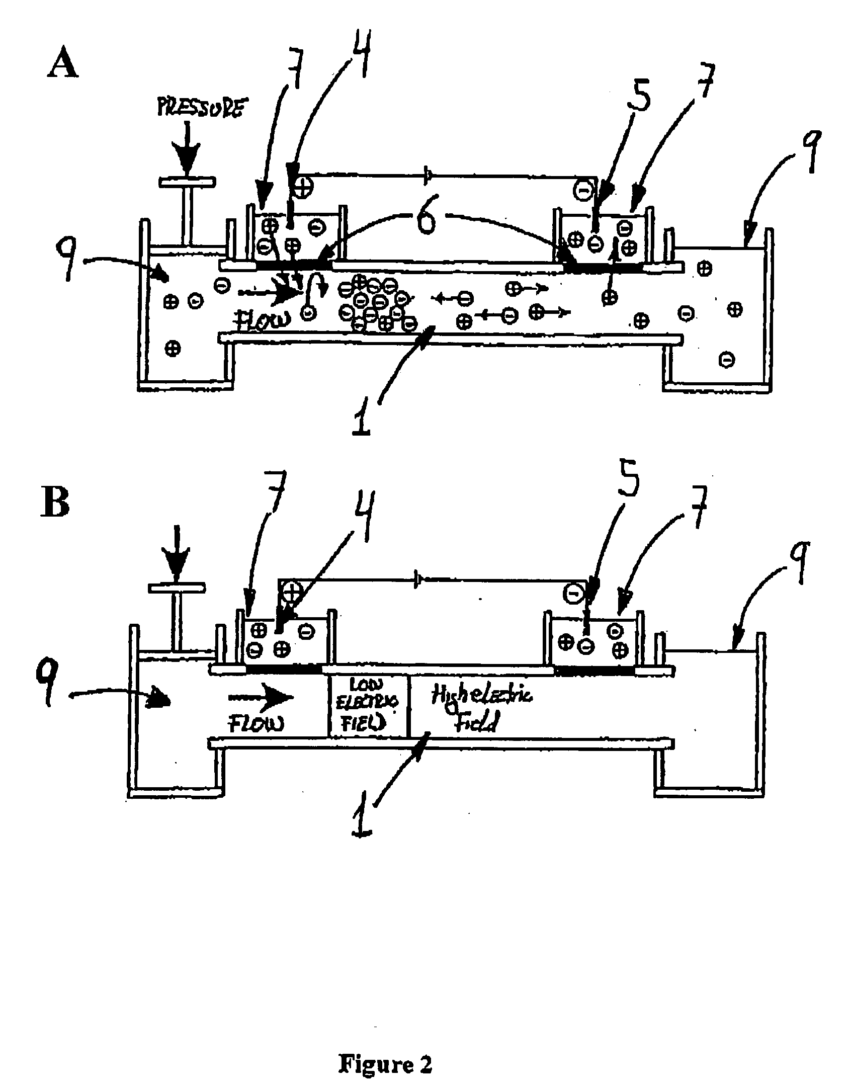
[0120] The system consists of a micrometer size flow channel made of PEEK tubing, which has two gap junctions covered by a cation-selective conductive membrane. The junction zones are placed into separate electrode buffer chambers. The PEEK tubing serves as electrophoretic channel and the cation-selective conductive membrane will not permit the exchange of anions between the buffer chambers and the fluidic channel. A syringe pump connected to the channel produces a flow stream (FIG. 3). Theoretically, having the anode at the upstream junction, negatively charged molecules will be attracted towards the upstream electrode and trapped there by the capture device.

[0121] The electrical junctions are made of Nafion tubing. Nafion is a poly(tetrafluoroethylene) poly...

example 2

Capture of Proteins

[0144] To compare the movement of slow anions with the theoretical model by visual observations, colored proteins such as myoglobin and hemoglobin were captured in the device (FIG. 6).

[0145] The protein band can be moved along the channel by changing the voltage or flow rate. For a given voltage, the protein band is situated more upstream if the flow rate is decreased (with lower overall current value) while the band is swept downstream if the flow rate is increased, resulting in higher overall current value. The maximum flow rate when the protein band is no longer captured was found to be 0.4 μL / min for an electric field of 187 V / cm (FIG. 6). This is in general agreement with the maximum current value, at 0.5 μL / min (FIG. 4). From these data, it can be assumed that at 0.4 μL / min the low conductive zone, which produces the stacking effect, is as short as possible to still achieve the capture effect, and at higher flow rates the band is swept out from the system....

example 3

Capture of DNA

[0147] In order to optimize the voltage and flow rate values, a solution of DNA was injected continuously into the device. An UV absorbance detector was positioned at the outlet of the device. Under this configuration, a decrease of the absorbance values represents that DNA is being captured. For optimization, different values of voltage were tested using a constant flow rate. A successful capture of DNA can be seen in FIG. 7. A decrease in the UV absorption at the detector shows that DNA is being captured. As soon as the electric field is turned off, a sharp band of the released DNA is observed.


PUM

PropertyMeasurementUnit
volumeaaaaaaaaaa
pHaaaaaaaaaa
flow ratesaaaaaaaaaa

Abstract

The invention relates to a method for capturing charged molecules of interest traveling in an electrolyte flow stream through an electrically non-conductive channel, comprising at least one anode and at least one cathode individually separated from said channel, but in electrical contact with said flow stream, by a conductive ion selective semi-permeable membrane. Said membrane interferes with the normal migration of ions towards its respective electrode, generating at least two zones of different electric field. Balance between hydrodynamic and electrical forces captures certain ions into the flow stream. it also relates to a device for performing the method.

Description

BACKGROUND OF THE INVENTION [0001] Biotech industries and laboratories are pushed to increase their productivity, efficiency and to lower their costs. Since most of the work involves liquid handling using a broad range of instruments and methods (e.g. pipettes, centrifuges, ovens, vortexes, chromatographic procedures and electrophoretic devices), the full integration of all these steps into a single analytical platform has become a tentative route to low-cost and high-throughput analysis. [0002] The concept of integration by miniaturization of analytical systems stems from the micro-scale electronic industry, which managed to integrate multiple electronic devices into centimeter scale structures to perform a multitude of electrical processes. Such devices are faster, cheaper and easily assembled for industrial scale production. From this field, terms such as microchannels, microfluidics and micropumps emerge as solutions for the integration of different analytical assays and methods...

Claims


Application Information

Patent Timeline
Patent Type & Authority Applications(United States)
IPC IPC(8): B01D57/02B01L3/00B81B3/00G01NG01N1/34G01N27/404G01N27/447
CPCB01L3/502753B01L2300/0681B01L2300/0864G01N2001/4016B01L2400/0487G01N1/405G01N27/44769B01L2400/0421G01N2001/4011
Inventor ASTORGA-WELLS, JUANPARK, SANG-RYOULSWERDLOW, HAROLDJESSON, GERALDLINDBERG, ULFBERGMAN, TOMASJORNVALL, HANSJONSSON, MATS
Owner PERKINELMER U S LLC
Why Eureka
Try Eureka