
Nuclear imaging system using rotating scintillation bar detectors with slat collimation and method for imaging using the same

a technology of scintillation bar and detector, which is applied in the field of nuclear medicine, can solve the problems of insufficient performance of bar detectors as designed in the prior art for use in medical imaging applications, inability to detect for use, and relatively low sampling capability of such scintillation crystals, etc., and achieve the effect of maximizing geometric efficiency

Active Publication Date: 2005-12-29
SIEMENS MEDICAL SOLUTIONS USA INC
View PDF8 Cites 19 Cited by
  • Summary
  • Abstract
  • Description
  • Claims
  • Application Information

AI Technical Summary

Benefits of technology

[0026] The present invention solves the existing need by providing a gamma camera detector constructed of a bundle of bar scintillators with slat collimator having a configuration that maximizes geometric efficiency with respect to signal-to-noise ratio (SNR) of observed photon information, and is optimized for many imaging modalities, and in particular for emission CT scanning.

Problems solved by technology

Additionally, because of the relatively small thickness dimension of the crystal (typically in the range of 0.5 to 2.5 cm) the sampling capability of such scintillation crystals is relatively low, in that a significant number of gamma photons emanating from an imaging subject will pass through the entire crystal without any interaction, and consequently cannot be detected for use is in constructing an image.
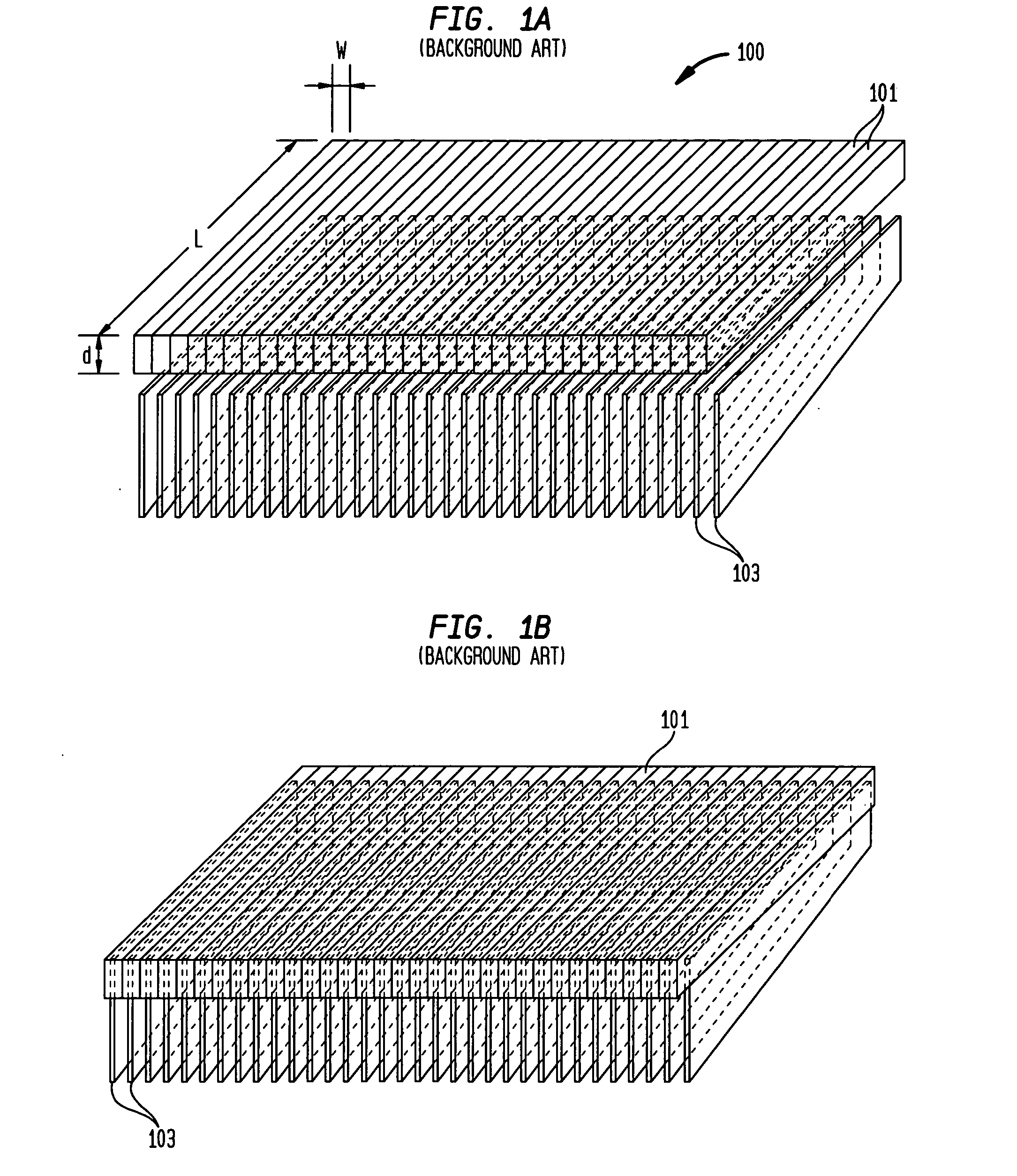
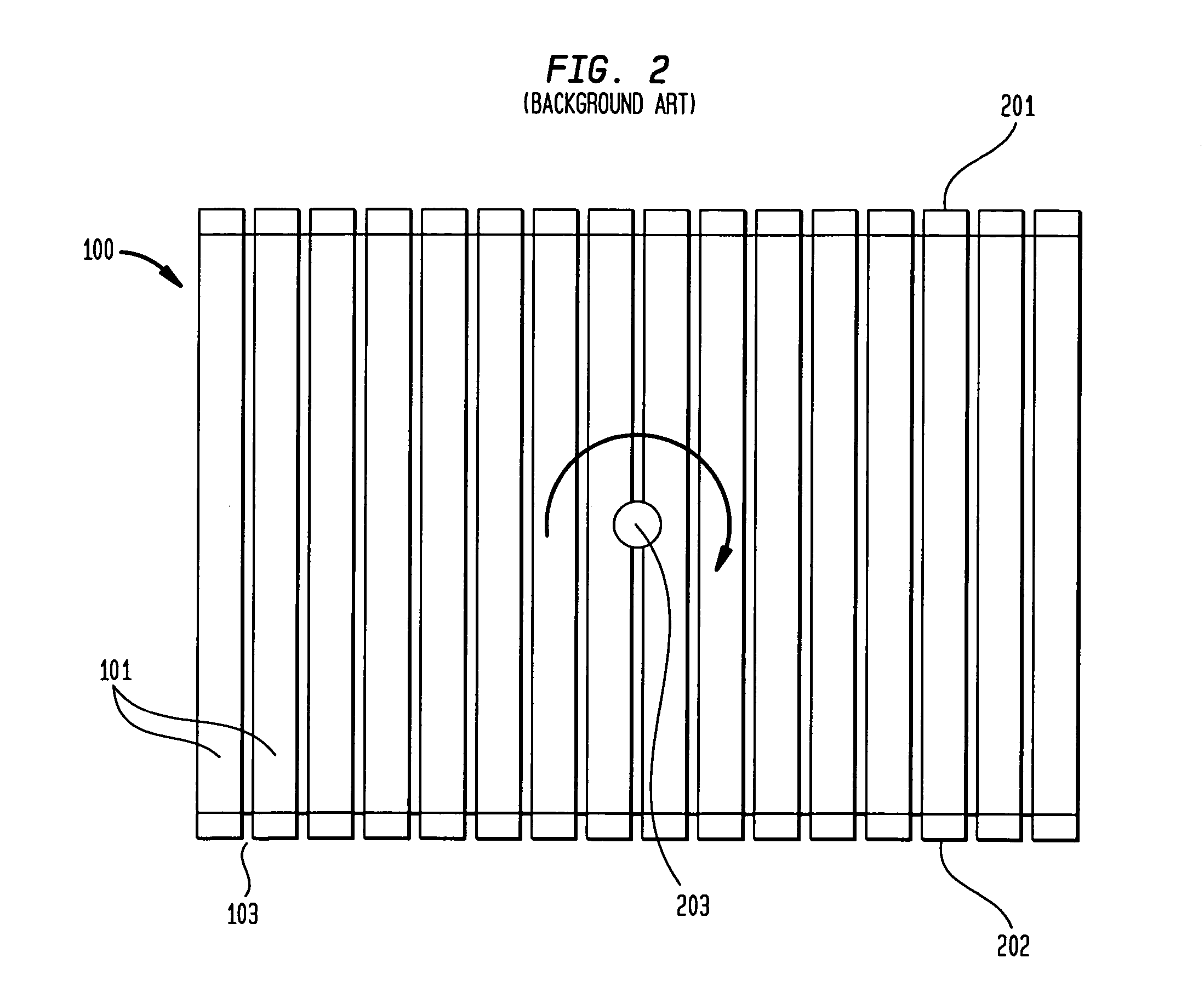
However, the performance of bar detectors as designed in the prior art is insufficient for use in medical imaging applications.

Method used


Image

  • Nuclear imaging system using rotating scintillation bar detectors with slat collimation and method for imaging using the same
  • Nuclear imaging system using rotating scintillation bar detectors with slat collimation and method for imaging using the same
  • Nuclear imaging system using rotating scintillation bar detectors with slat collimation and method for imaging using the same

Examples


Embodiment Construction

[0037]FIG. 4 shows the basic components of detector modules (i.e., a photosensor, collimator slats and a bar scintillator) and their assembled structures according to the present invention. Two different module types are proposed based on the coupling location of the photosensors on the bar scintillator. The type I module has a photosensor located at the middle-bottom of the scintillator, while the type II module has two photosensors, one mounted on each end. The type I and type II modules each have pros and cons in terms of electronic processing requirements, cost and performance characteristics.

[0038] In order to maximize light collection efficiency (LCE), each individual bar scintillator preferably is polished and wrapped with reflective materials such as MgO, TiO2 or Teflon®, except for the area where the photosensor is coupled. The bar scintillator then is embedded between two elongated slats made from thin film tungsten or lead. This configuration prevents intercrystal scatte...


PUM


Abstract

A gamma camera having a scintillation detector formed of multiple rotating bar detector modules arranged in a ring configuration, with synchronized spin motion of each module. Such a camera can be used for both PET (coincidence) and single photon imaging applications. Image reconstruction is obtained using either an inverse 3-D Radon transform or a 3-D fan-beam algorithm.

Description

BACKGROUND OF THE INVENTION [0001] 1. Field of the Invention [0002] The present invention generally relates to nuclear medicine, and systems for obtaining nuclear medicine images of a patient's body organs of interest. In particular, the present invention relates to a novel detector configuration for nuclear medical imaging systems that are capable of performing either positron emission tomography (PET) or planar and single photon emission computed tomography (SPECT). [0003] 2. Description of the Background Art [0004] Nuclear medicine is a unique medical specialty wherein radiation is used to acquire images that show the function and anatomy of organs, bones or tissues of the body. Radiopharmaceuticals are introduced into the body, either by injection or ingestion, and are attracted to specific organs, bones or tissues of interest. Such radiopharmaceuticals produce gamma photon emissions that emanate from the body. One or more detectors are used to detect the emitted gamma photons, ...

Claims


Application Information

Patent Timeline
IPC IPC(8): G01T1/161G01T1/164
CPCA61B6/037G01T1/1644
Inventor JOUNG, JINHUN
Owner SIEMENS MEDICAL SOLUTIONS USA INC
Learn More