Method for service chaining in a communication network
- Summary
- Abstract
- Description
- Claims
- Application Information
AI Technical Summary
Benefits of technology
Problems solved by technology
Method used
Image
Examples
Embodiment Construction
[0048] Reference will now be made in detail to the embodiments of the present invention, examples of which are illustrated in the accompanying drawings.
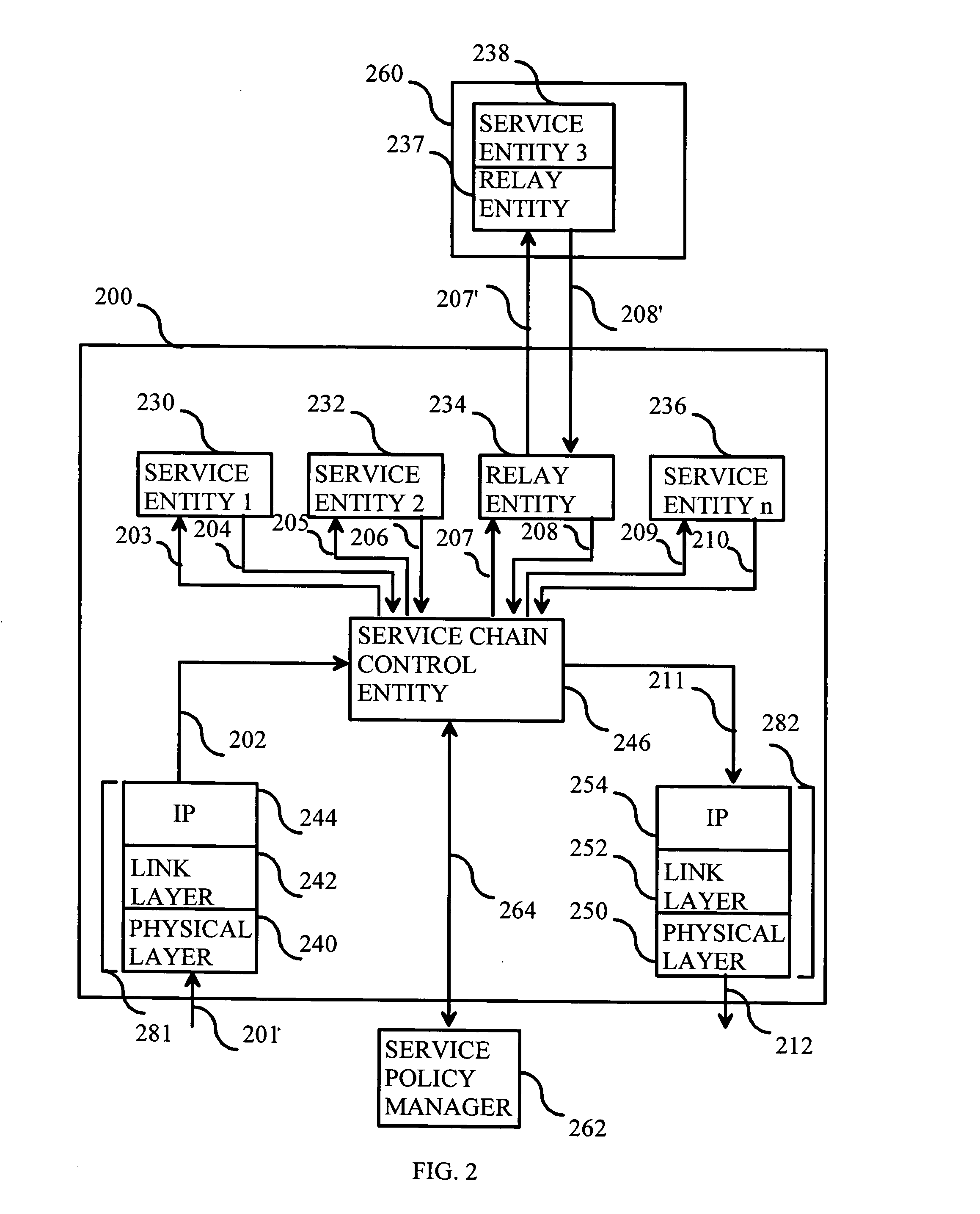
[0049]FIG. 2 is a block diagram illustrating a system comprising a network node, which is configured to provide several logical service entities, according to the invention. In FIG. 2 there is a network node 200, which comprises an incoming protocol stack 201 for receiving IP packets and an outgoing protocol stack 212 for sending IP packets. Network node 200 may be an IP router, an access router, an edge router or a general-purpose server computer for processing packet data. Incoming and outgoing protocol stacks 201 and 212 comprise physical layer entities 240 and 250, link layer entities 242 and 252, and IP layer entities 244 and 254, respectively. The physical layer entities provide, for example, optical fiber connectivity. The link layer entities provide, for example, Synchronous Digital Hierarchy (SDH), Synchronous Optical Netwo...
PUM
 Abstract
Description
Claims
Application Information
 - R&D
- Intellectual Property
- Life Sciences
- Materials
- Tech Scout
- Unparalleled Data Quality
- Higher Quality Content
- 60% Fewer Hallucinations
Browse by: Latest US Patents, China's latest patents, Technical Efficacy Thesaurus, Application Domain, Technology Topic, Popular Technical Reports.
© 2025 PatSnap. All rights reserved.Legal|Privacy policy|Modern Slavery Act Transparency Statement|Sitemap|About US| Contact US: help@patsnap.com


