Indirect-direct evaporative cooling system operable from sustainable energy source

a technology of sustainable energy source and evaporative cooling system, which is applied in the direction of air humidification system, lighting and heating apparatus, heating type, etc., can solve the problem of water dribbling down in a rather uncontrolled fashion out of the slots, and achieve the effect of reducing power consumption, high efficiency cooling, and facilitating the use of twin power sources

Inactive Publication Date: 2006-01-05
SPEAKMAN
View PDF17 Cites 23 Cited by
  • Summary
  • Abstract
  • Description
  • Claims
  • Application Information

AI Technical Summary

Benefits of technology

[0009] Indirect/direct evaporative coolers are well suited for operation with sustainable energy, particularly solar power. More particularly, IDECs operate best in low humidity climates such as those found in the southwest quadrant of the United States. These areas of the country, coincidentally, have long periods of continuous sunshine that can be used to power solar panels. Thus, the marriage of solar power and IDECs offers a unique opportunity for cooling homes, offices, work places and factories in that portion of the United States at minimum cost because most operating power can be supplied by the sun. One form of solar panel suitable for use in this invention is that offered by First Solar, LLC Perryburg, Ohio (www.firstsolar.com). Even without solar power, the IDEC disclosed herein provides highly efficient cooling with about an eighty percent (80%) reduc

Problems solved by technology

The water exiting those slots dribbles down in a rather

Method used


Image

  • Indirect-direct evaporative cooling system operable from sustainable energy source
  • Indirect-direct evaporative cooling system operable from sustainable energy source
  • Indirect-direct evaporative cooling system operable from sustainable energy source

Examples


Embodiment Construction

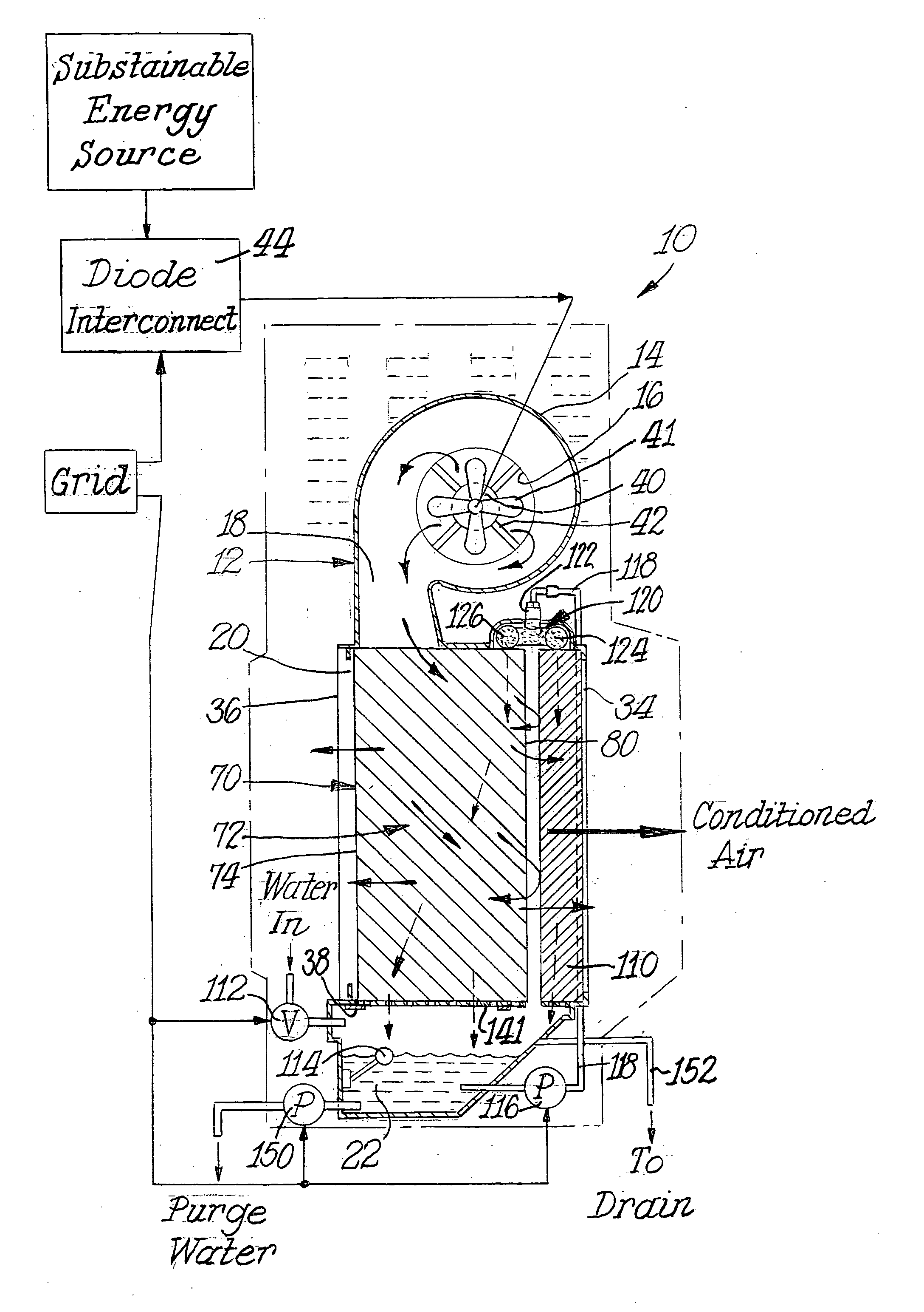
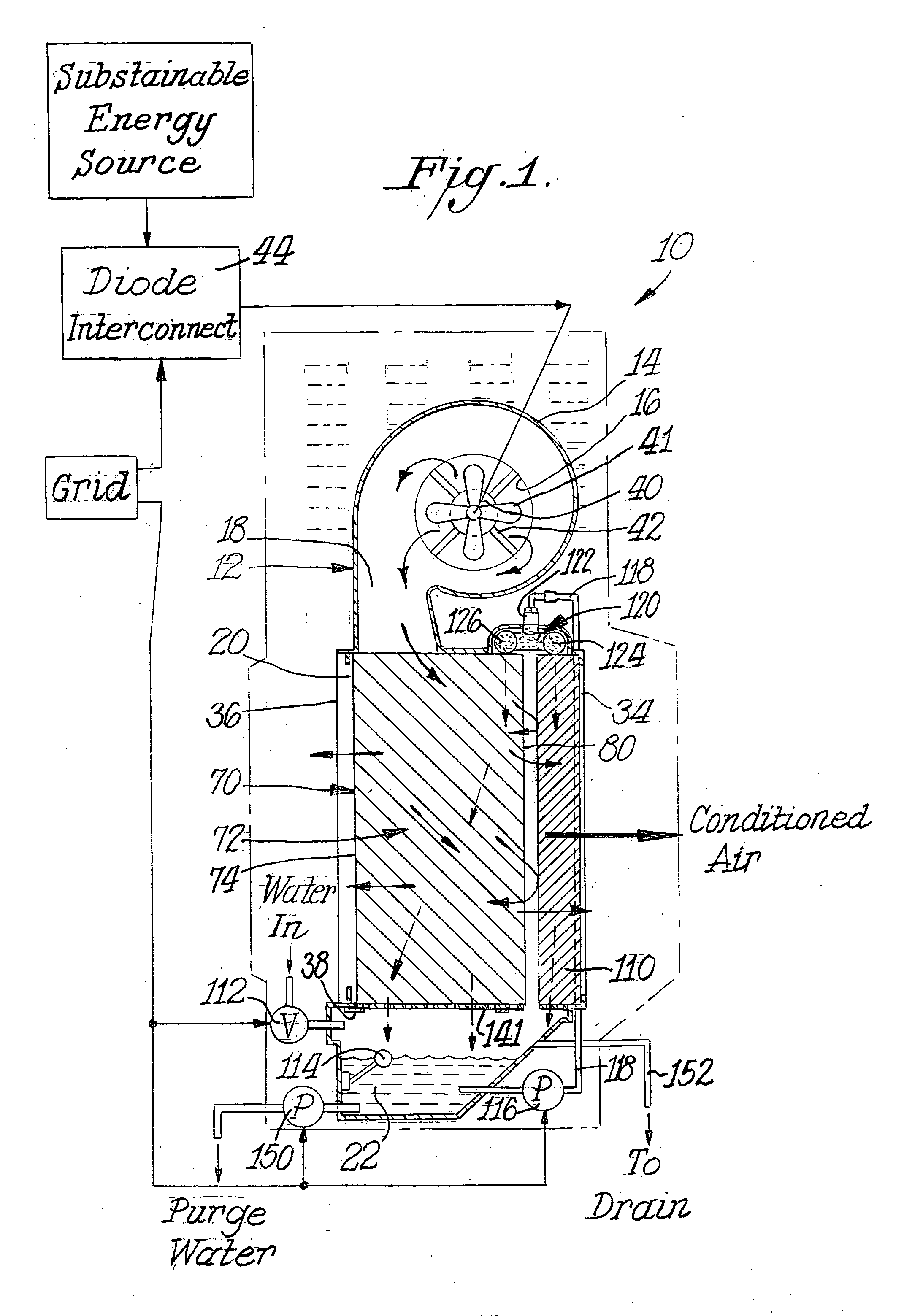
[0032] The basic components of applicants' IDEC 10 are schematically illustrated in FIG. 1. These components are preferably housed in a cabinet 12 which is molded as a single plastic part as shown in FIG. 2. This one piece plastic construction of the cabinet 12 promotes ease of manufacture and reduces corrosion issues as noted in Davis II. This approach also facilitates assembly and replacement of parts in the cabinet of 12.

[0033] For simplicity sake, the arrangement and function of basic sections of the cabinet 12 will be described in a top-to-bottom sequence. The upper end 14 (as viewed in FIG. 1) of the cabinet 12 has a volute shape with a generally circular outside air inlet 16 and a larger, generally rectangular air outlet discharge 18. The air outlet discharge 18 transitions into the larger, generally rectangular cross-sectional body 20 of cabinet 12. A reservoir chamber 22 at the bottom of cabinet 12 rounds out the basic sections of the cabinet 12, which is preferably formed...


PUM


Abstract

Improved means for powering and increasing evaporative cooling in an indirect-direct evaporative cooling (IDEC) apparatus are disclosed. Sustainable energy from solar energy mixed with grid power, when needed, power the IDEC device. These DC and AC power sources are seamlessly merged in a unique diode interconnect unit. Improved means for evaporative cooling include a rayon-based flocking on the wet side of molded plastic indirect evaporative cooling plates. Separate wet and dry passages through those plates are facilitated by a unique means for clamping the upper ends of the plates. These clamping means also add to the structural integrity of an array of plates so that the array can be inserted in and removed from a housing containing other operational components of the IDEC such as fan, direct cooling plates and water distribution means. Applicants IDEC utilizes improved porous piping that allows uniform and continuous distribution of water to all wet passages within both the indirect and direct stages of the IDEC. Operational controls for the system limit the potential water damage caused by overflow of water from the IDEC housing.

Description

CROSS REFERENCE TO RELATED APPLICATIONS [0001] Not applicable. BACKGROUND OF THE INVENTION [0002] This invention relates to a highly efficient system and apparatus for supplying conditioned air to an interior space. The system utilizes two stage evaporative cooling to deliver conditioned air to living and work spaces, namely indirect and direct cooling stages. Such cooling is often identified by the acronym IDEC which stands for indirect / direct evaporative cooling. This invention seamlessly draws operating power from multiple AC and DC sources including a utility power grid and / or sustainable energy sources such as solar panels. A unique combination of indirect stage heat exchanger plate coatings and water distribution manifolds enhances the operation of the IDEC apparatus used in the system. [0003] Other IDEC systems are described below. For example, U.S. Pat. No. 5,664,433 issued Sep. 9, 1997 to Davis Energy Group, Inc. (“Davis I”) describes an indirect-direct evaporative cooling ...

Claims


Application Information

Patent Timeline
IPC IPC(8): F25B27/00F28D5/00F24F1/0071
CPCF24F5/0035F24F5/0046Y02B30/545F24F2006/046F28D5/02F24F2001/0092F24F1/0007Y02B30/54F24F1/0071
Inventor HYLAND, SAMUELLOBOZO, ROBERT F.STANWICK, COVINGTON
Owner SPEAKMAN
Why Eureka
Try Eureka