Electric machine with integrated electronics in a circular/closed-loop arrangement

a technology of electric machines and electronics, applied in the direction of electronic switching, fixed capacitors, pulse techniques, etc., can solve the problems of potential reliability problems, not snubbing capacitance, etc., and achieve the effect of minimizing inductance and maximizing capacitan

Inactive Publication Date: 2006-01-05
VISTEON GLOBAL TECH INC
View PDF28 Cites 29 Cited by
  • Summary
  • Abstract
  • Description
  • Claims
  • Application Information

AI Technical Summary

Benefits of technology

[0011] In a further aspect of the present invention, a dielectric layer is disposed between the positive and negative bus bars and located between a substantially flat surface on the positive bus bar and a substantially flat surface on the negative bus bar. The dielectric layer electrically isolates the positive bus bar from the negative bus bar. The thickness of the positive bus bar, the negative bus bar, and the dielectric layer may be minimized to maximize the capacitance and minimize the inductance between the positive and negative bus bar.

Problems solved by technology

Therefore, filtering and snubbing capacitance is not equally shared among the switch circuits, due to the asymmetric layout of the circuit board.
The unequal sharing of such capacitance may cause slight timing delays between the switch circuits, exposing certain switches to an unequal amount of current thereby overloading the switch during the delay and causing potential reliability issues.

Method used


Image

  • Electric machine with integrated electronics in a circular/closed-loop arrangement
  • Electric machine with integrated electronics in a circular/closed-loop arrangement
  • Electric machine with integrated electronics in a circular/closed-loop arrangement

Examples


Embodiment Construction

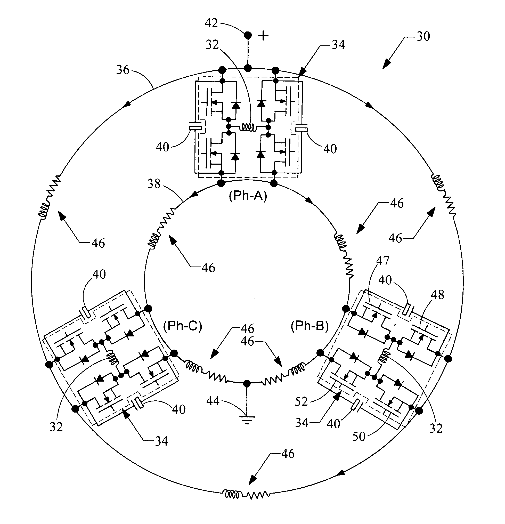
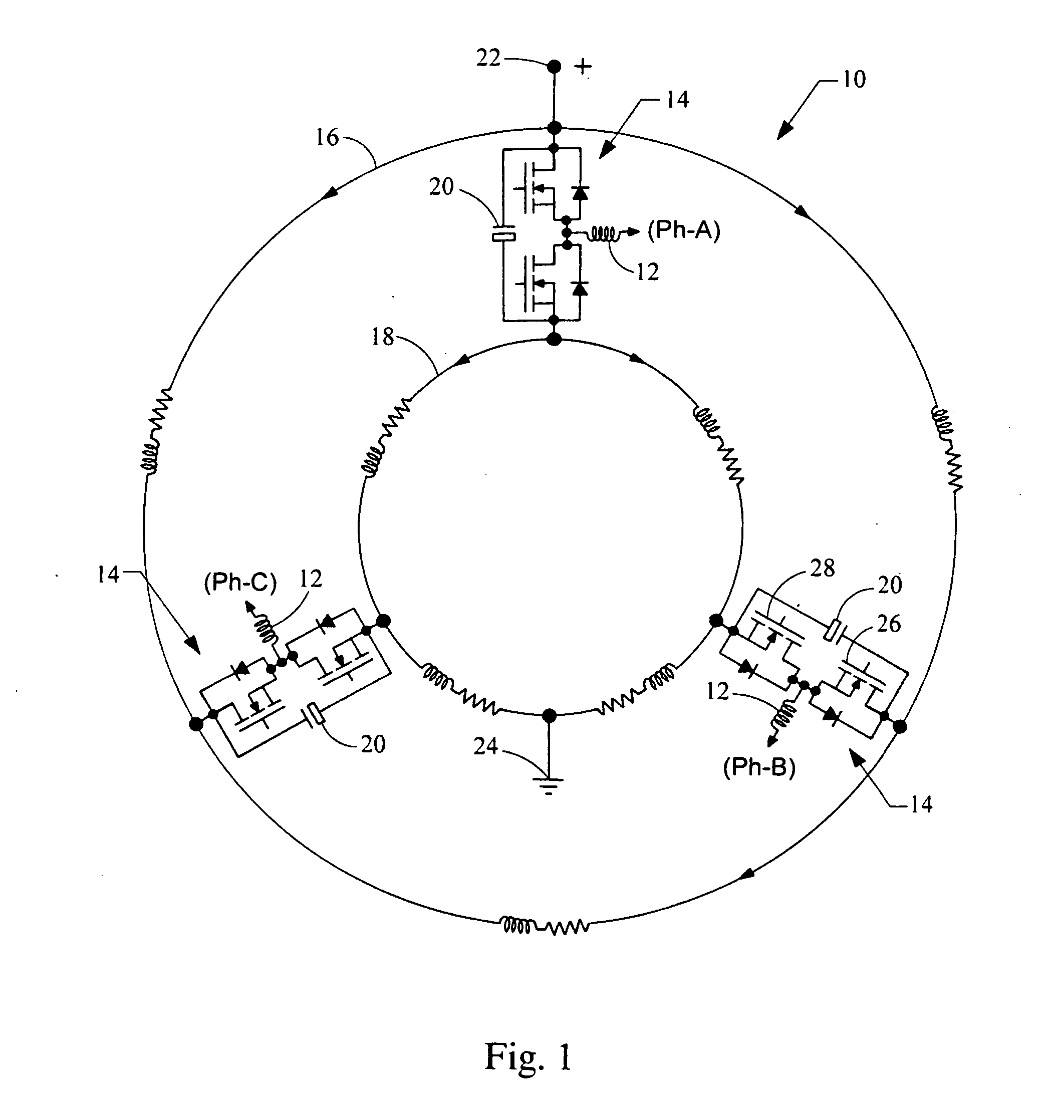
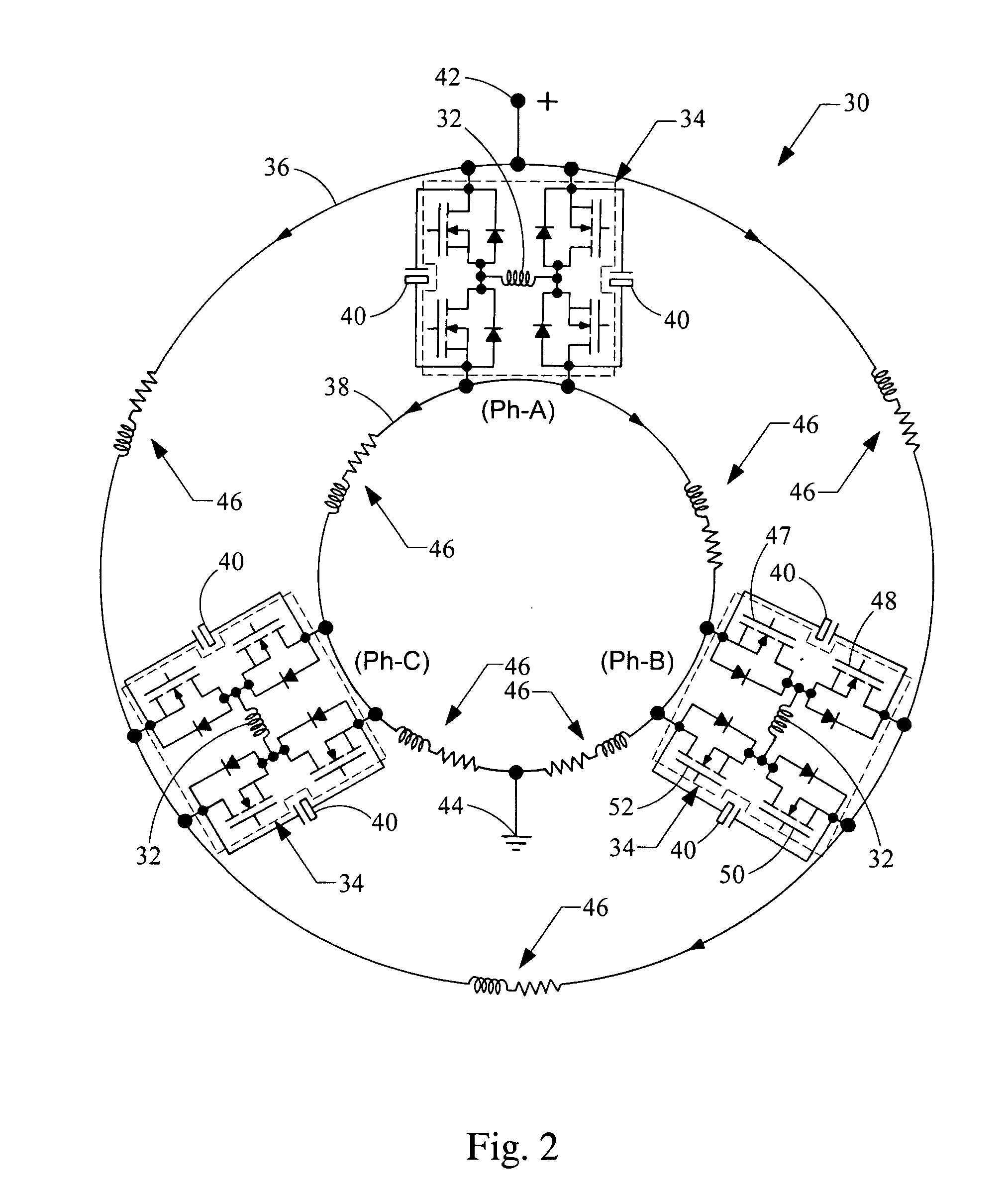
[0018] Referring now to FIG. 1, an electrical machine embodying the principles of the present invention is illustrated therein and designated at 10. The electrical machine 10 includes windings 12, switch circuits 14, a positive bus bar 16 and a negative bus bar 18. In the configuration shown, for a three phase permanent magnet or induction machine, one switching circuit 14 is connected to each phase or winding 12 to selectively energize each of the windings 12.

[0019] The switch circuit 14 is connected between the positive bus bar 16 and the negative bus bar 18. Each switch circuit 14 is shown as a half bridge configuration. As such, a first MOSFET 26 is connected between the positive bus bar 16 and the winding 12. Similarly, a second MOSFET 28 is connected between the winding 12 and the negative bus bar 18. Each of the MOSFETs 26 and 28 are controlled by a gate driver circuit (not shown) to energize the windings 12 of the electric machine 10. Although each switch circuit 14 is show...


PUM


Abstract

An electric machine including multiple windings, a switch circuit connected to each of the windings, a positive bus bar, and a negative bus bar. The switch circuits are in communication with the windings to selectively energize each of the windings. The positive bus bar is a conductive plate connected to the switch circuits and the negative bus bar is a conductive plate positioned substantially parallel to the positive bus bar and connected electrically to the switch circuits.

Description

BACKGROUND [0001] 1. Field of the Invention [0002] The present invention generally relates to a bus bar configuration for an electric machine. [0003] 2. Description of Related Art [0004] Electric machines and switch configurations for controlling electrical machines are well developed in the art. Typically, the switching electronics are packaged and mounted separately from the electric machine. With the switching electronics and electric machine typically connected through multiple connectors and a wire harness, it is advantageous to reduce the number of connectors and wire harnesses to improve system reliability and decrease system cost. In addition, the elimination of such connections reduces electrical noise and cross talk between adjacent electrical systems. [0005] Conventionally, a bus bar and switch circuits are laid out linearly on a circuit board in a open loop configuration. The open loop or linear arrangement of the switch circuits causes the distance between each switchin...

Claims


Application Information

Patent Timeline
Patent Type & Authority Applications(United States)
IPC IPC(8): H01G4/34H01G4/00
CPCH02K3/28H03K17/6874H02P25/18H02K11/0073H02K11/33
Inventor ANWAR, MOHAMMAD N.TEIMOR, MEHRDADLUKEN, RICHARD E.BRAUTIGAN, JEFFREY J.
Owner VISTEON GLOBAL TECH INC
Why Eureka
Try Eureka