Backlight unit

a backlight unit and backlight technology, applied in the field of backlight units, can solve the problems of inability to actively cope with the miniaturization and reduction of the weight requirements of electronic appliances, limited by the weight and volume long use time of the backlight unit, so as to enhance the thermal reliability, improve the light efficiency, and suppress the effect of temperature ris

Inactive Publication Date: 2006-01-05
LG DISPLAY CO LTD
View PDF13 Cites 65 Cited by
  • Summary
  • Abstract
  • Description
  • Claims
  • Application Information

AI Technical Summary

Benefits of technology

[0028] An object of the invention is, in part, to provide a backlight unit provided with multiple LEDs having a cooling structure that can optimally suppress the temperature rise to enhance the thermal reliability and increase the light efficiency to thus simultaneously increase brightness and decrease power consumption.

Problems solved by technology

However, CRT technology has failed to actively cope with the miniaturization and reduced weight requirements of electronic appliances due to the weight and volume of CRTs.
In other words, the CRT is limited by its weight and volume, which is disadvantageous to the trend toward miniaturization and reduced weight of electronic appliances.
However, the LCD employing the direct type backlight is generally used in a large-sized monitor, i.e., a television or the like, and its usage time is significantly long.
Also, the LCD employing the direct type backlight uses a number of lamps, and the lamps may be disordered or lose durability, so that they may not turn on.
However, an LCD employing the direct type backlight has multiple lamps installed below the LCD panel, and if one lamp does not turn on due to the loss of durability or failure, a portion where the lamp is not turned on becomes noticeably dark compared with other portions.
Thus the portion where the lamp is not turned on is a visible defect on the display.
Also, the backlight includes a drawback arising from light efficiency being lowered due to disassembly and assembly of the fluorescent lamps or heat generation.
Since the LEDs have a lower light efficiency than the related art CCFLs (cold cathode fluorescent lamps), they consume much more power than the related art CCFLs, which results in the generation of much heat.
This 80 to 90° C. temperature range is higher by about 40° C. than the temperature range of the backlight unit provided with CCFLs, and serves as a serious drawback by causing deformation of the optical sheets, by destroying LED junctions, by decreasing the light efficiency of LEDs, and by degenerating the liquid crystal material to seriously decrease the reliability of the main parts of the display.

Method used


Image

  • Backlight unit
  • Backlight unit
  • Backlight unit

Examples


Embodiment Construction

[0047] Reference will now be made in detail to the preferred embodiments of the present invention, examples of which are illustrated in the accompanying drawings.

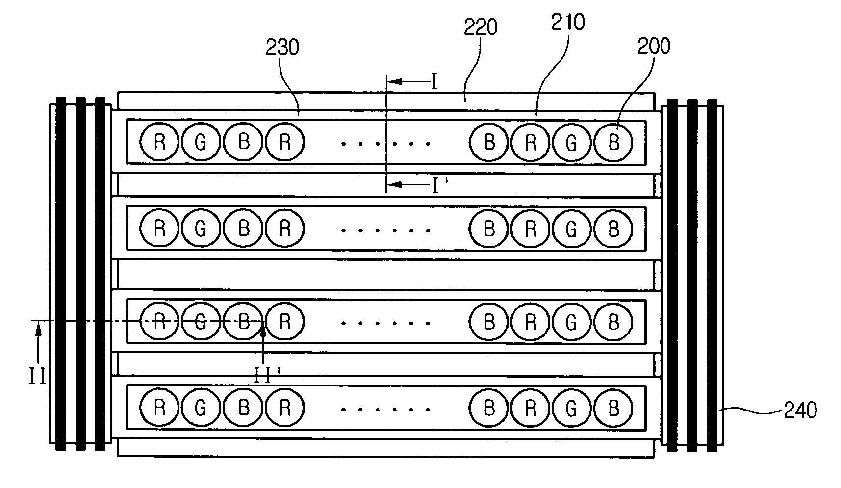
[0048]FIG. 2A shows plane view of a backlight unit of an LCD according to the invention, FIG. 2B shows a sectional view taken along the line I-I′ of FIG. 2A, and FIG. 2C shows a sectional view taken along the line II-II′ of FIG. 2.

[0049] Referring to FIGS. 2A through 2C, the direct type backlight unit includes multiple LEDs 200 for generating light, a printed circuit board (PCB) 210 disposed below the LEDs 200, and a bottom cover 220 over which the PCB 210 is mounted. Optical sheets 250 include a diffusion sheet for diffusing the light generated by the LEDs 200. A heat pipe 230 is disposed in the form of a plate between the PCB 219 and the bottom cover 220, and a heat sink 240 is disposed outside the bottom cover 220, for radiating heat generated from the LEDs 200 and transmitted to the heat pipe 230 to the outside. The b...


PUM


Abstract

A backlight unit is provided with LEDs having a cooling structure. The backlight includes a heat pipe, which is disposed below a PCB having the LEDs thereon, and a heat sink connected with the heat pipe. Heat generated from the LEDs conducts via the PCB and the heat pipe and is then radiated by the heat sink. The cooling performance of the backlight unit is thus enhanced and the temperature increase in the light emission region is thus suppressed, so that thermal reliability of the LEDs is enhanced and light efficiency is increased to increase the brightness and to decrease the power consumption.

Description

CROSS-REFERENCE OF APPLICATION [0001] This application claims priority under 35 U.S.C. §119 of Korean Patent Application No. 48799 / 2004 filed Jun. 28, 2004, the entire contents of which are hereby incorporated by reference. BACKGROUND OF THE INVENTION [0002] 1. Field of the Invention [0003] The invention relates to a backlight unit, and more particularly, to a backlight unit provided with a light emitting diode (LED) having a cooling structure. [0004] 2. Description of the Related Art [0005] Generally, a cathode ray tube (CRT) is one of the displays usable as a monitor of a television, a meter, an information terminal or the like. However, CRT technology has failed to actively cope with the miniaturization and reduced weight requirements of electronic appliances due to the weight and volume of CRTs. In other words, the CRT is limited by its weight and volume, which is disadvantageous to the trend toward miniaturization and reduced weight of electronic appliances. [0006] To solve the...

Claims


Application Information

Patent Timeline
Patent Type & Authority Applications(United States)
IPC IPC(8): F21V7/04
CPCF21Y2101/02F21V29/006G02F2001/133628G02F1/133603F28D15/0275F28D15/04F21V29/51F21V29/70F21Y2115/10G02F1/133628G02F1/1335
Inventor JEONG, IN SUKKIM, GI BIN
Owner LG DISPLAY CO LTD
Why Eureka
Try Eureka