
Battery pack

a battery pack and battery technology, applied in the field of batteries, can solve the problems of high reactivity of lithium, very likely to catch fire or explode, and material that is used as the negative electrode and the non-aqueous electrolyte is flammable, and achieves the effect of increasing the attachment strength

Active Publication Date: 2006-01-05
SAMSUNG SDI CO LTD
View PDF4 Cites 18 Cited by
  • Summary
  • Abstract
  • Description
  • Claims
  • Application Information

AI Technical Summary

Benefits of technology

[0020] The present invention provides a battery pack that has increased attachment strength of a protective circuit module molded by a resin on top of a battery including an electrode assembly, a can, and a cap assembly.
[0021] The present invention is advantageous in that a reinforcement groove that is formed on a lead plate couples to the molded portion which comprises the protective circuit module therein thus increasing the bond strength of the molded portion to the battery. In addition, the reinforcement groove holds the molded portion in place even when it is subjected to a force in the lateral direction and prevents it from being twisted.

Problems solved by technology

When a malfunction such as an internal short circuit occurs, the energy that has accumulated in the battery is discharged quickly and may result in a fire or explosion.
In the widely-used lithium-based rechargeable batteries, the lithium itself has a high reactivity and is very likely to catch on fire or to explode when the battery malfunctions.
However, the materials that are used as the negative electrode and the non-aqueous electrolyte are flammable and are very likely to catch fire or to explode when the battery malfunctions.
It is generally difficult to couple the electrode of a battery to the electrical terminal of a protective circuit module by direct welding because of the shape and composition of the battery.

Method used


Image

  • Battery pack
  • Battery pack
  • Battery pack

Examples


Embodiment Construction

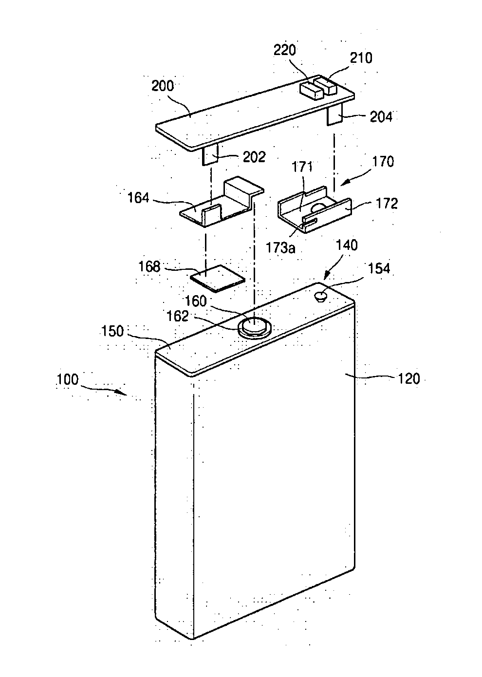
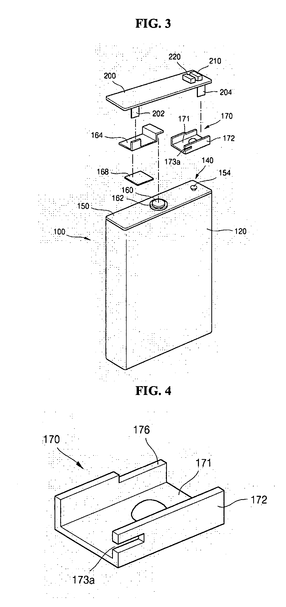
[0035]FIG. 3 is an exploded perspective view of a battery pack according to an exemplary embodiment of the present invention

[0036] A can-type battery pack according to the present invention, as shown in FIG. 3 includes a battery 100 and a protective circuit module 200. The battery 100 includes a can 120 that contains an electrode assembly (not shown in the drawings) and is sealed by a cap assembly 140.

[0037] The battery pack may further comprise a molded portion (not shown in FIG. 3) that is formed on the top of the battery to mold it with the protective circuit module.

[0038] The can 120 for a rectangular lithium ion battery is a metallic container that has a prismatic shape with an open top. It is generally made of aluminum or an aluminum alloy that is lightweight and resists corrosion. The can 120 acts as a container for the electrode assembly which includes a positive electrode, a separator, and a negative electrode, as well as for an electrolyte. The electrode assembly is ins...


PUM

PropertyMeasurementUnit
strengthaaaaaaaaaa
sizeaaaaaaaaaa
weightaaaaaaaaaa

Abstract

A battery pack has increased attachment strength of a protective circuit module molded from a resin on top of a rechargeable battery including an electrode assembly, a can, and a cap assembly. The reinforcement groove that is formed on the lead plate retains the molded portion, which has the protective circuit module therein, and increases the strength of the molded portion to the battery.

Description

CROSS REFERENCE TO RELATED APPLICATION [0001] This application claims priority to and the benefit of Korean Patent Application No. 2004-0046269, filed on Jun. 21, 2004, which is hereby incorporated by reference for all purposes as if fully set forth herein. BACKGROUND OF THE INVENTION [0002] 1. Field of the Invention [0003] The present invention relates to a battery pack. In particular, the present invention relates to a battery pack that has increased attachment strength of a protective circuit module that is molded by a resin and is positioned on top of a battery that comprises an electrode assembly, a can, and a cap assembly. [0004] 2. Description of the Prior Art [0005] Recently, rechargeable batteries have been widely researched and developed because they can be manufactured in a compact size and can provide significant amounts of voltage. Typical examples of rechargeable batteries that have recently been developed include nickel-hydrogen (Ni-MH) batteries, lithium (Li) batteri...

Claims


Application Information

Patent Timeline
Patent Type & Authority Applications(United States)
IPC IPC(8): H01M2/02H01M2/08H01M6/50H01M50/50H01M50/528H01M50/574
CPCH01M2/20H01M2200/00H01M2/34H01M2/22Y02E60/10H01M50/50H01M50/528H01M50/574
Inventor LIM, HONG SUP
Owner SAMSUNG SDI CO LTD
Learn More