
Integrated power plant and system and method incorporating the same

a power plant and integrated technology, applied in the field of power plants, can solve the problems of reducing the performance of the system, reducing the thermal efficiency of the typical gasifier combined cycle power plant, and consuming a large amount of gasifier carbon dioxide,

Active Publication Date: 2006-01-05
CUMMINS ENTERPRISE LLC
View PDF3 Cites 24 Cited by
  • Summary
  • Abstract
  • Description
  • Claims
  • Application Information

AI Technical Summary

Problems solved by technology

However, all these types of power plants have several disadvantages.
For example, a typical gasifier combined cycle power plant has a low thermal efficiency, approximately 40 percent.
Furthermore, there may be a large amount of carbon dioxide produced by the gasifier in addition to the fuel.
However, removing the carbon dioxide from the fuel before the fuel is combusted in order to reduce carbon dioxide emissions significantly reduces the performance of the system.
Furthermore, the fuel cells that are used in such plants do not consume all of the fuel that is fed into the fuel cell, thereby reducing the efficiency of the system.

Method used


Image

  • Integrated power plant and system and method incorporating the same
  • Integrated power plant and system and method incorporating the same

Examples


Embodiment Construction

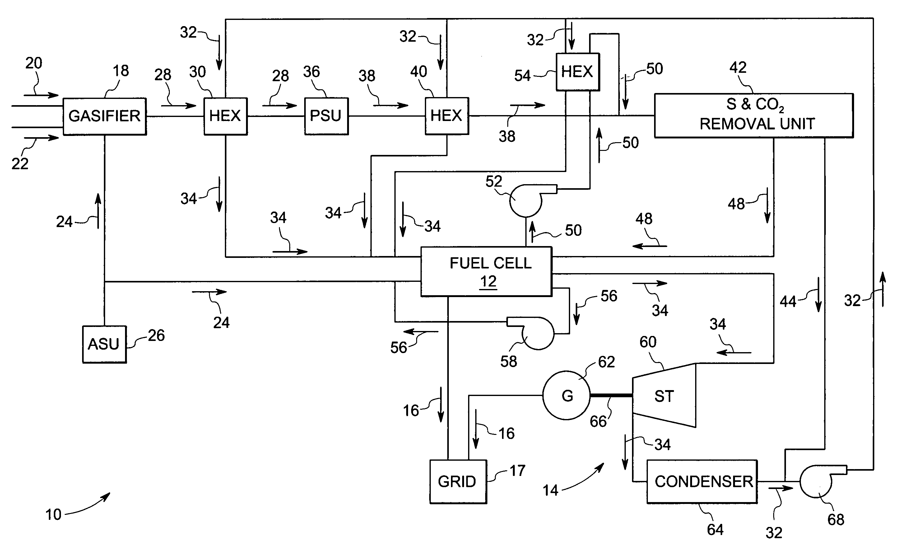
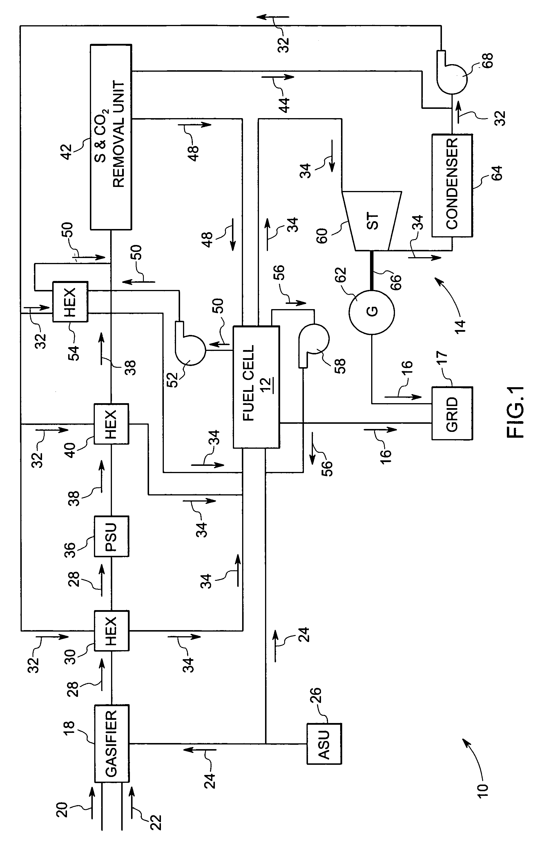
[0014] Referring now to FIG. 1, an exemplary integrated power plant 10 comprising a fuel cell 12 and a steam turbine system 14 is illustrated. In this embodiment, the fuel cell 12 and the steam turbine system 14 are each operable to supply electricity 16 to an electrical grid 17. The illustrated power plant 10 also comprises a gasifier 18. The gasifier 18 is supplied with coal 20 and steam 22 for reaction therein. In addition, in the illustrated embodiment, the gasifier 18 receives oxygen 24 from an air separation unit (ASU) 26 that separates the oxygen 24 from nitrogen and other gaseous components of air. The reaction in the gasifier 18 involves a multi-stage combustion of coal 20 in the presence of steam 22 and oxygen 24 to produce a fuel 28 comprising hydrogen and carbon monoxide for the fuel cell 12.

[0015] The use of substantially pure oxygen 24 in the gasifier 18 is more desirable than the use of air. Atmospheric air has a relatively high concentration of nitrogen, which is la...


PUM


Abstract

A system and method for producing electricity is described. The system comprises a fuel cell assembly. The system may comprise a steam turbine and a generator. The fuel cell assembly may be used to provide heat to produce the steam used to power the steam turbine. The system may comprise a gasifier that is operable to produce a fuel for use in the fuel cell assembly. The system may comprise an air separation unit that is operable to supply oxygen to the gasifier and to the fuel cell assembly for reaction with the fuel. The oxygen that is not reacted in the fuel cell assembly may be recirculated through the fuel cell assembly. Spent fuel from the fuel cell assembly may be recirculated through the fuel cell assembly. A carbon dioxide removal system may be used to remove carbon dioxide from the fuel upstream of the fuel cell.

Description

BACKGROUND [0001] The invention relates generally to power plants producing electricity from coal or other solid or low grade liquid fuels and more specifically to an integrated gasification power plant including a fuel cell and a steam turbine power plant. [0002] A variety of different systems have been used to generate electrical power from coal and low grade fuels. One such system is an integrated gasification gas turbine combined cycle power plant (IGCC). In this system a conventional gas turbine combined cycle power plant utilizes combustion of the gasified fuel to induce rotation of gas turbine blades coupled to a shaft that is coupled to a generator. The generator converts the rotational energy produced by the turbine into electrical energy. The fuel for combustion in the turbine may be provided by a gasifier, which produces a gaseous fuel from a solid fuel, such as coal or other solid or low grade liquid fuels (e.g. biomass, heavy oils). The exhaust waste heat can be recover...

Claims


Application Information

Patent Timeline
IPC IPC(8): H01M8/04H01M8/06
CPCH01M8/04014H01M8/04097H01M8/04111H01M8/04164H01M8/0643H01M8/0662Y02E60/525H01M8/0675H01M2008/1293H01M2250/402Y02E60/50Y02B90/12H01M8/0668Y02B90/10
Inventor BALAN, CHELLAPPASMITH, DANIEL PRESTON
Owner CUMMINS ENTERPRISE LLC
Learn More