System for tissue cavity closure

a tissue cavity and tissue technology, applied in the field of tissue cavity closure systems, can solve the problems of significant bleeding, inability to adequately create the desired suture stitch, abrasion and trauma between the metallic staple and the soft tissue surface, etc., to achieve less invasive treatment, prevent tissue expansion, and reduce the volume of the atria

Inactive Publication Date: 2006-01-05
ATRICURE
View PDF7 Cites 364 Cited by
  • Summary
  • Abstract
  • Description
  • Claims
  • Application Information

AI Technical Summary

Benefits of technology

[0010] Embodiments of the invention relate to devices and methods for less invasive treatment of atrial fibrillation or other application involving placing a pledgeted mattress suture stitch to compress opposing tissue together or prevent tissue expansion. More particularly, certain embodiments of the invention relate to appendage isolation suturing devices that enable reducing the volume of the atria, or isolating the atrial appendage to prevent clots from forming in the cavity and dislodging into an embolus capable of causing a thromboembolic event (e.g. stroke, myocardial infarction, pulmonary embolus, peripheral embolus). Furthermore the invention offers a means of improving hemodynamics during atrial fibrillation treatment procedures by virtue of its efficient operation avoidance of a requirement for bypass support.
[0011] Aspects of the invention also enable appendage isolation procedures to be performed less invasively through limited incisions that previously required large, open incisions with inherent morbidity and risks to other anatomic structures. The appendage isolation suture devices according to the present invetion are capable of altering the geometry of an atrial appendage (or other soft tissue structure), via a median sternotomy, lateral thoracotomy, intercostals port-access, mini-sternotomy, other less invasive approaches involving subxiphoid access, inguinal approaches, or sub-thoracic approaches adjacent the diaphram. It should be noted that, thought the disclosure makes reference to sutures, the devices herein may be affixed with other fastening devices and / or fastening means. Such devices and / or means being readily understood by those skilled in the art. Alternatively, the appendage isolation suturing devices according to the present invention can be modified for catheter-based applications by reconfiguring the device, and incorporating other feature tailored for intravascular access. As such, the inventive devices and methods may enable patients to undergo therapeutic surgical procedures while enduring less pain, expedited hospital stays, and shorter rehabilitative and recovery times.
[0013] In the present invention, methods and devices are provided in which one or more deformable or resilient needles, and suture (one, two, or multiple strands) are passed through the atrial appendage (or other tissue) during a less invasive procedures. It should also be noted that the needles described herein may be standard needles that are attached to sutures. Furthermore, the invention contemplates sutures having stiffened ends which effectively function as needles. To accomplish this, the subject devices advance or retract needles (deformable or superelastic) such that they can be compressed into small lumens incorporated in a grasper having a small cross-sectional profile to facilitate utility during less invasive access procedures. Use of the needles enable advancing or retracting suture material through the atrial appendage and creating pledgeted stitches that distribute the stresses exerted by the stitch against the treated soft tissue.
[0014] In forming these subject product structures, one or more suture strands is advanced (sequentially or simultaneously) through the atrial appendage at a single location or multiple strategically distributed locations. The reinfoced pledgets employed direct the compression of the treated anatomical structure to distribute the stresses applied by the stitches along a larger tissue surface. As such, the embodiments of the invention provide isolation devices capable of creating pledgeted stitches that increase reliability of the stitch, distribute the applied forces over a much greater length of soft tissue, and—in the case of performing an atrial appendage isolation procedure—ensure consistent closure of the appendage orifice. Embodiments of the invention also enable contacting and penetrating the atrial appendage, for creating pledgeted stitches capable of isolating the atrial appendage (or closing any other anatomic cavity), during less invasive access to anatomic regions where exposure is compromised by the confined space or difficult to reach anatomic surface.

Problems solved by technology

However, during beating heart procedures and minimally invasive access to the heart commonly associated with mini-sternotomies, mini-thoracotomies, port access, and subxiphoid access, such manual surgical techniques require too much time, are accompanied with significant bleeding, and are not able to adequately create the desired suture stitch to completely close the orifice into the atrial appendage.
The stapling approach, however successful, causes abrasion and trauma between the metallic staple and the soft tissue surface.
These approaches leave foreign material exposed to blood flow which material increases the risk of thromboembolism and increases the possibility that patients undergoing this procedure still require anticoagulation regimen such as Coumadin to prevent clots from forming in the heart.
In addition, the risk of dislodgement for such patches is high, whether associated with fracture of the patch attachment means, degradation of the patch materials, mechanical damage to the device during manual compression of the heart (e.g. CPR) or other unexpected mechanical manipulation.
Any dislodgement of such patch-type devices is life-threatening.
These approaches either do not adequately attach the isolation device to the tissue surface or are associated with high stresses at the attachment point, which can lead to tissue abrasion, tearing, or other unwanted tissue response.

Method used


Image

  • System for tissue cavity closure
  • System for tissue cavity closure
  • System for tissue cavity closure

Examples


embodiment 109

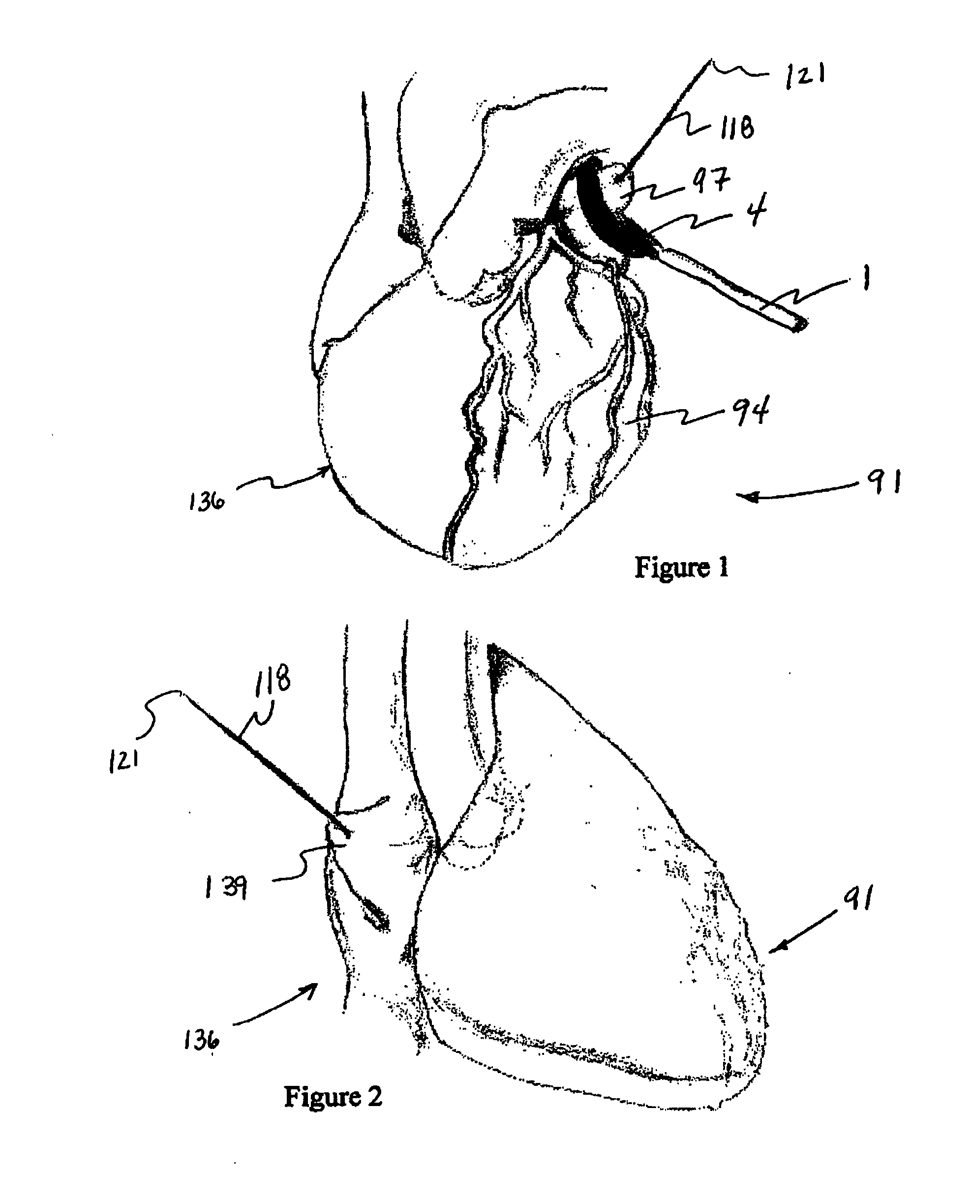
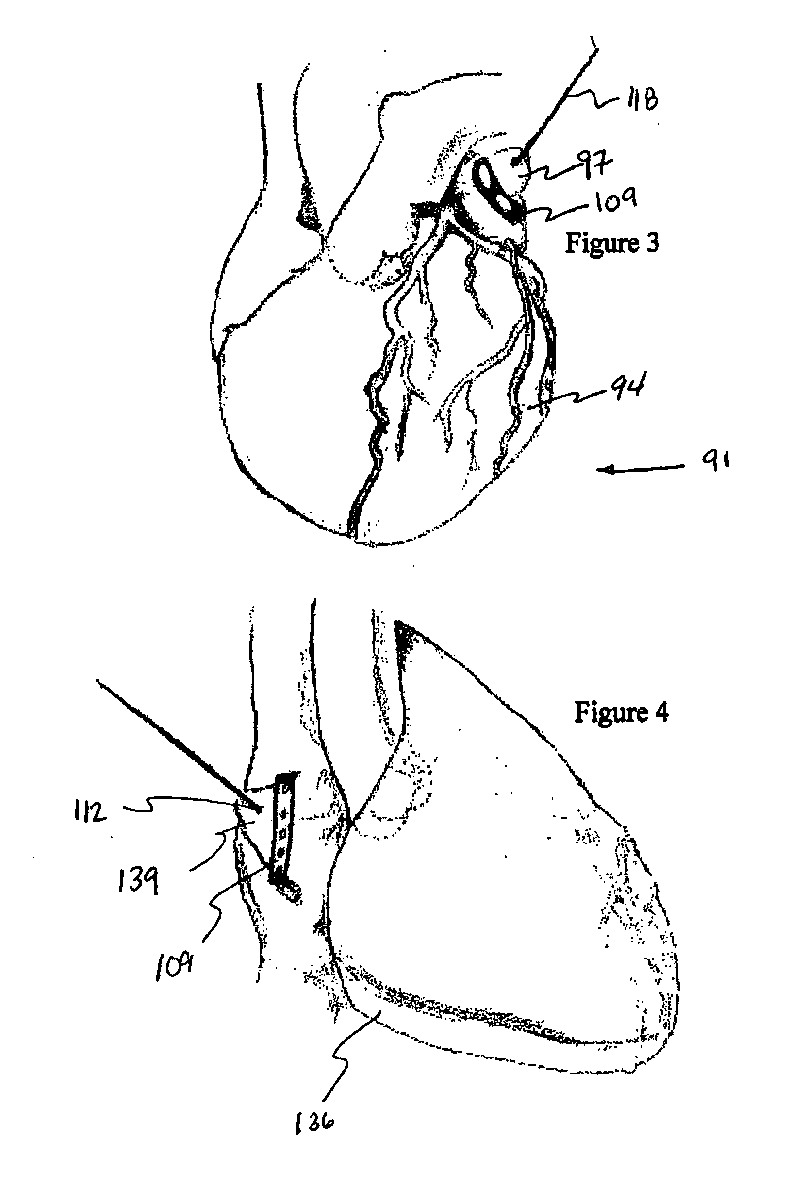
[0040]FIG. 3 shows a side view of heart 91 that contains pledgeted stitch 109 isolating left atrial appendage 97 by juxtaposing opposing endocardial walls of left atrium 94 between two reinforced pledgets 109 such that clots within and the trabeculated interior surface of the left atrial appendage is separated from blood flow. In addition, left atrial volume is significantly reduced. Each suture strand 118 extends from outside the first reinforced pledget where continuous length of strand 115 defines an anchor, through an opening or puncture site in the first reinforced pledget, through the juxtaposed atrial walls, through an opening or puncture site in the second reinforced pledget, and outside the second reinforced pledget where suture strand free ends are tied into a knot or otherwise anchored to prevent relaxation of tightened stitch 112. Once the stitch is tightened, the reinforced pledgets are positioned intimately against the epicardial surfaces of the left atrial appendage a...

embodiment 1

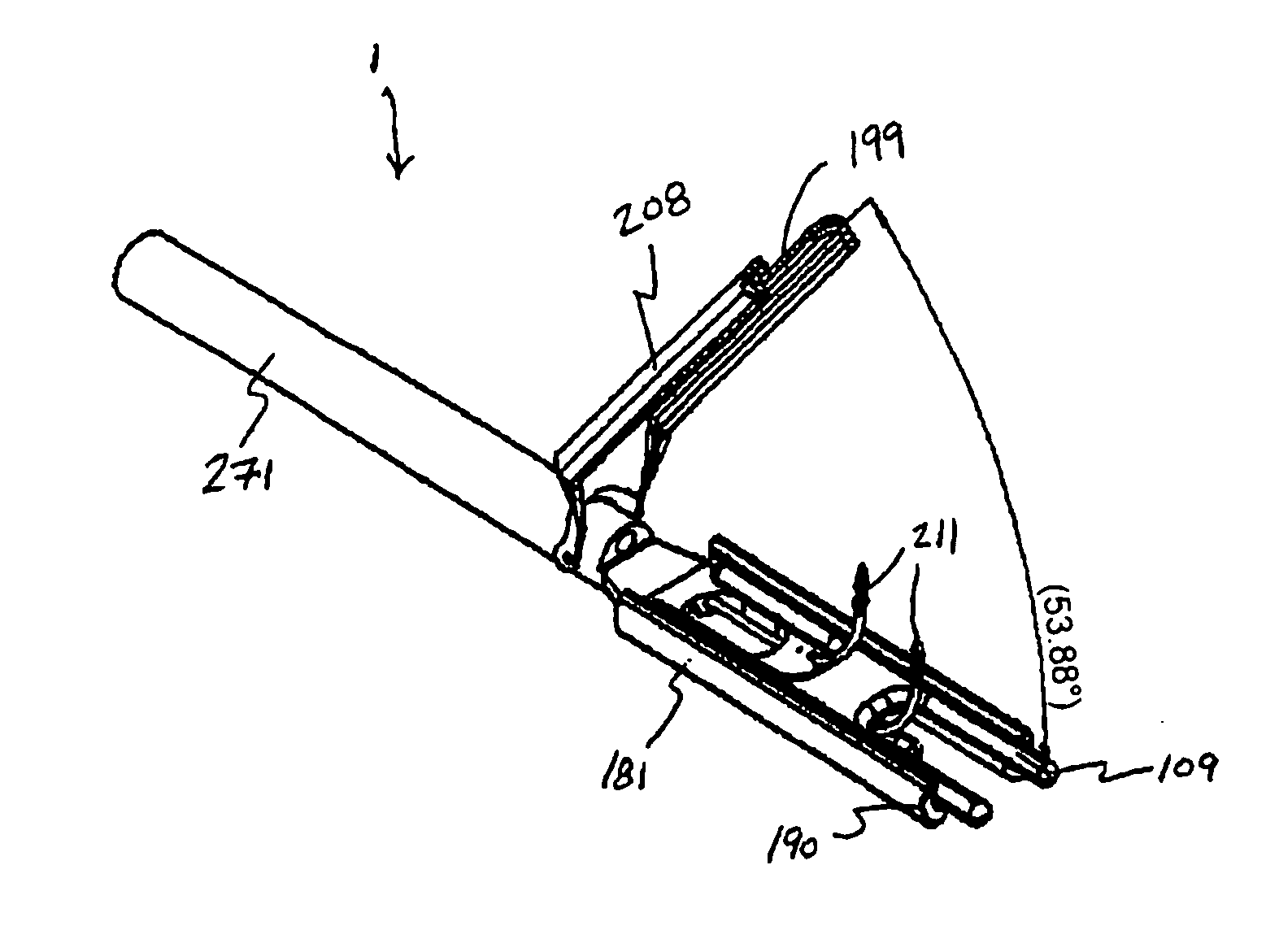
[0042] In embodiment 1 in FIGS. 5A to 5D and FIGS. 6A to 6C, appendage isolation grasper 1 is shown with single reinforced pledget 109 housed in lower jaw 181 (upper jaw 208 does not show a reinforced pledget purely for illustration purposes; in practice the upper jaw may or may not contain a reinforced pledget, depending on the application), and two resilient (or deformable) needles 211. FIGS. 5A to 5D show the grasper with the jaws in a closed orientation and with two resilient (or deformable) needles fully deployed. FIGS. 6A to 6C show the grasper with the upper jaw in an open orientation.

[0043] Appendage isolation grasper 1 incorporates two lumens into which the needles are compressed into a low profile for insertion through trocar, cannulae, or introducer. Lower jaw 181 incorporates two separate channels 190 associated with confining lumens and containing exit points 195 through which needles 211 pass. The lower jaw channels are curved to guide / direct the needles upward through...

embodiment 451

[0056]FIGS. 11A to 11C show a perspective view, a top view and a side view of another reinforced pledget embodiment 451. This reinforced pledget embodiment incorporates two openings 454 separated by an axially oriented central link 457 and defining spaces through a support structure 463 through which suture strand free ends 121 are advanced using actuated needles 211 of appendage isolation system 1. The length (“I2”) of the central link is chosen based on the distribution requirements. As the flattened profile increases, the length of the central link is increased to accommodate the desire to distribute the forces along a greater length. The openings through the support structure match channel exit point spacing 193 for the grasper.

[0057]FIGS. 12A to 12C show a perspective view, a top view and a side view of a reinforced pledget embodiment 496. This reinforced pledget embodiment is fabricated from a resilient polymer through which suture strand free ends 121 can be advanced using ac...


PUM


Abstract

Surgical systems for less invasive access to and isolation of an atrial appendage are provided. A suturing grasper compresses soft tissue structures and deploys one or more sutures through complimentary pledget(s) carried by the grasper. The pledgets are reinforced, containing support members that define the profile of the stitch and distribute stresses applied by the stitch, once tightened, over a length of tissue. This hardware may be applicable to other surgical and catheter based applications as well including: compressing soft tissue structures lung resections and volume reductions; gastric procedures associated with reduction in volume, aneurysm repair, vessel ligation, or other procedure involving isolation of, resection of, and reduction of anatomic structures.

Description

RELATED APPLICATION [0001] This application is a non-provisional of U.S. Provisional Application No. 60,580,890 filed Jun. 18, 2004, the entirety of which is incorporated by reference.FIELD OF THE INVENTION [0002] This invention relates to devices and methods for less invasive treatment of atrial fibrillation or other application involving placing a pledgeted mattress suture stitch(es) to compress opposing tissue or to prevent its expansion. BACKGROUND OF THE INVENTION [0003] Surgical atrial fibrillation treatment involves eliminating the electrical propagation wavelets that trigger and sustain atrial fibrillation, and mitigating the risk of stroke by reducing the volume of enlarged the atria through isolation or resection of the atrial appendages. A previous surgical technique for resecting an atrial appendage involves manually advancing a suture, via an attached, curved, fixed needle, through the atrial appendage. This approach is performed under direct visualization during open h...

Claims


Application Information

Patent Timeline
Patent Type & Authority Applications(United States)
IPC IPC(8): A61B17/122
CPCA61B17/0401A61B17/0469A61B17/0643A61B17/10A61B17/122A61B2017/0647A61B2017/00243A61B2017/00349A61B2017/0404A61B2017/0406A61B2017/0472A61B17/1285
Inventor WHAYNE, JAMES G.FLEISCHMAN, SIDNEY D.
Owner ATRICURE
Why Eureka
Try Eureka