
Cooling system for an internal combustion engine with exhaust gas recirculation (EGR)

a technology of internal combustion engine and cooling system, which is applied in the direction of machines/engines, mechanical equipment, non-fuel substance addition to fuel, etc., can solve the problems of increasing the cost of egr and cooling system, engine may not be able to use a larger egr cooler, and the nosub>x /sub> reduction is not easy to achiev

Active Publication Date: 2006-01-12
INT ENGINE INTPROP CO LLC
View PDF6 Cites 44 Cited by
  • Summary
  • Abstract
  • Description
  • Claims
  • Application Information

AI Technical Summary

Benefits of technology

[0012] The cooling system may have a coolant pump, a front cover, a crankcase, a cylinder head, and an EGR cooler. The coolant pump is mounted on the front cover. The front cover forms a crankcase supply conduit connected to an outlet side of the coolant pump. The front cover forms a coolant inlet connected to the inlet side of the coolant pump. The crankcase is connected to the front cover. The crankcase forms a coolant channel, a crankcase inlet, and one or more crankcase outlets. The crankcase inlet and the crankcase outlets are connected to the coolant channel. The crankcas...

Problems solved by technology

A larger EGR cooler may increase the costs of the EGR and cooling systems.
Some engines may not be able to use a larger EGR cooler due to space limitations.
These engines may have less exhaust gas recirculation, which may result in lower NOx reduction.

Method used


Image

  • Cooling system for an internal combustion engine with exhaust gas recirculation (EGR)
  • Cooling system for an internal combustion engine with exhaust gas recirculation (EGR)
  • Cooling system for an internal combustion engine with exhaust gas recirculation (EGR)

Examples


Embodiment Construction

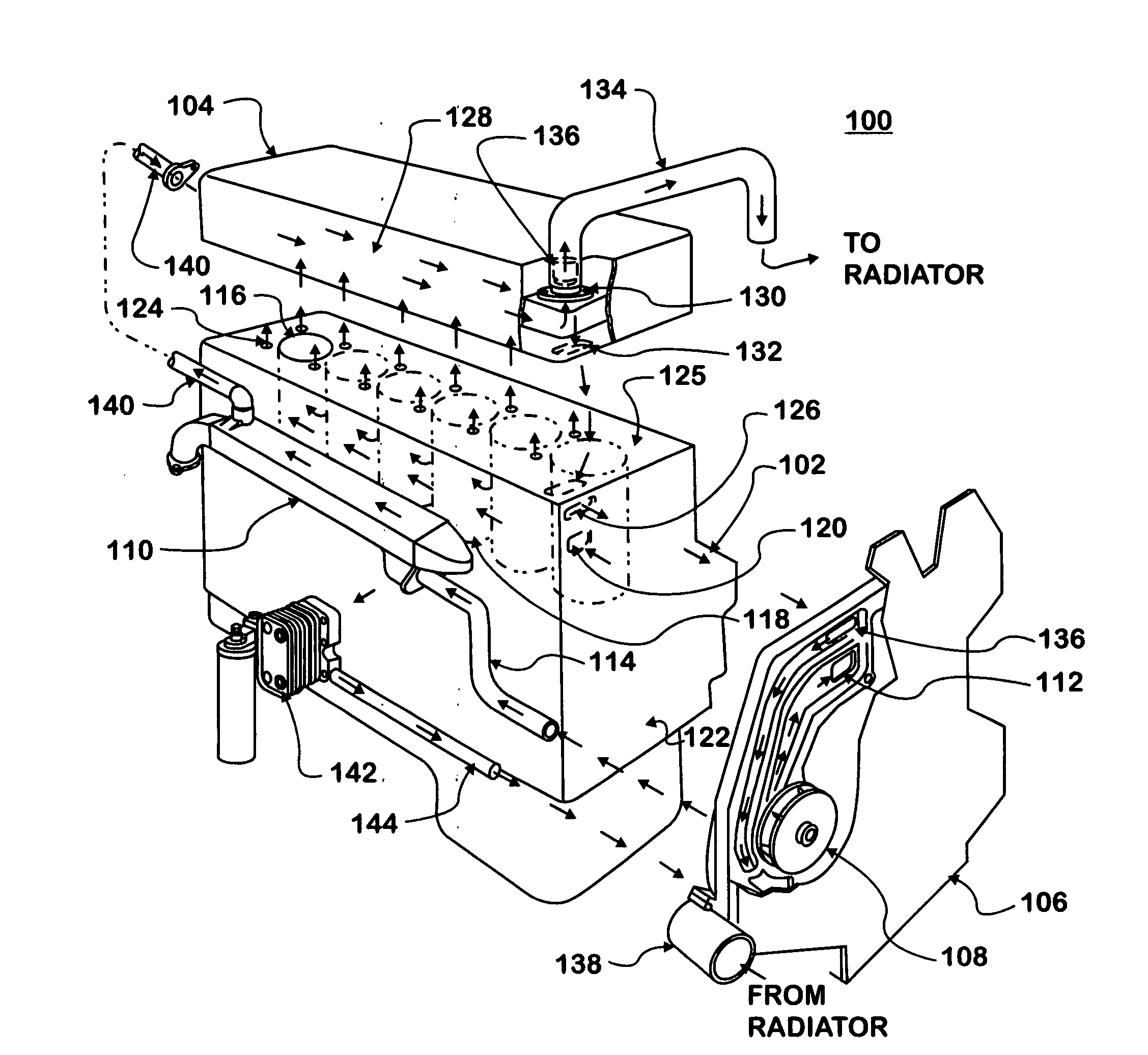
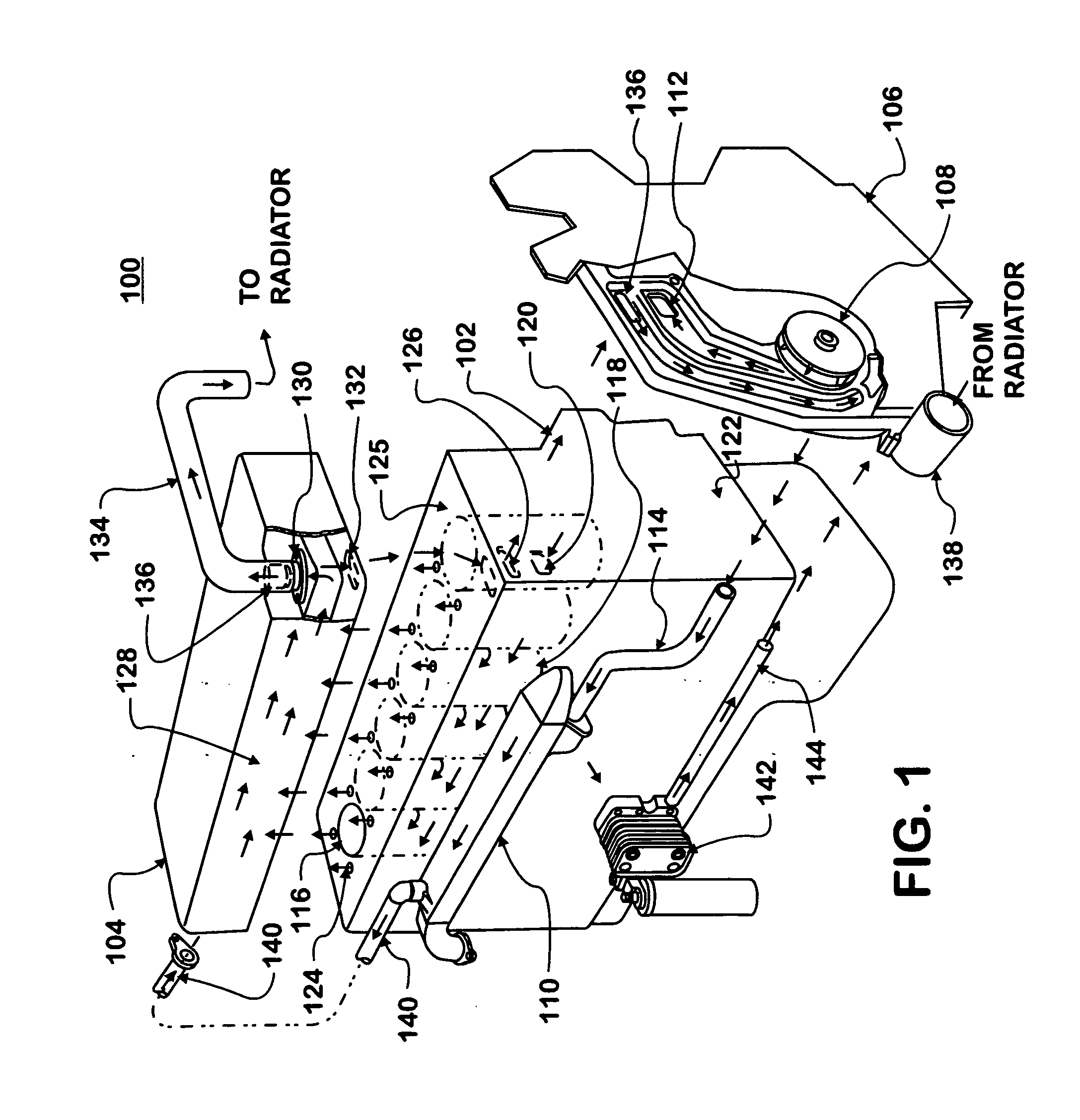
[0018]FIG. 1 is an expanded, perspective view of a cooling system 100 in an internal combustion engine with exhaust gas recirculation (EGR). The internal combustion engine has a crankcase 102, a cylinder head 104, and a front cover 106. The internal combustion engine may have other components and configurations. The cooling system 100 circulates coolant through the engine to remove heat from the engine. The coolant may be water, an antifreeze compound like ethylene glycol, a combination thereof, or the like. The cooling system 100 has a coolant pump 108 in the front cover 106. The coolant pump 108 has parallel connections to the crankcase 102 and an EGR cooler 110. Parallel connections include separate and non-sequential conduits where coolant flows at essentially the same time and at essentially the same temperature. The coolant pump 108 pumps coolant to the crankcase 102 through a crankcase supply conduit 112 formed by the front cover 106. The coolant pump 108 pumps coolant to the...


PUM


Abstract

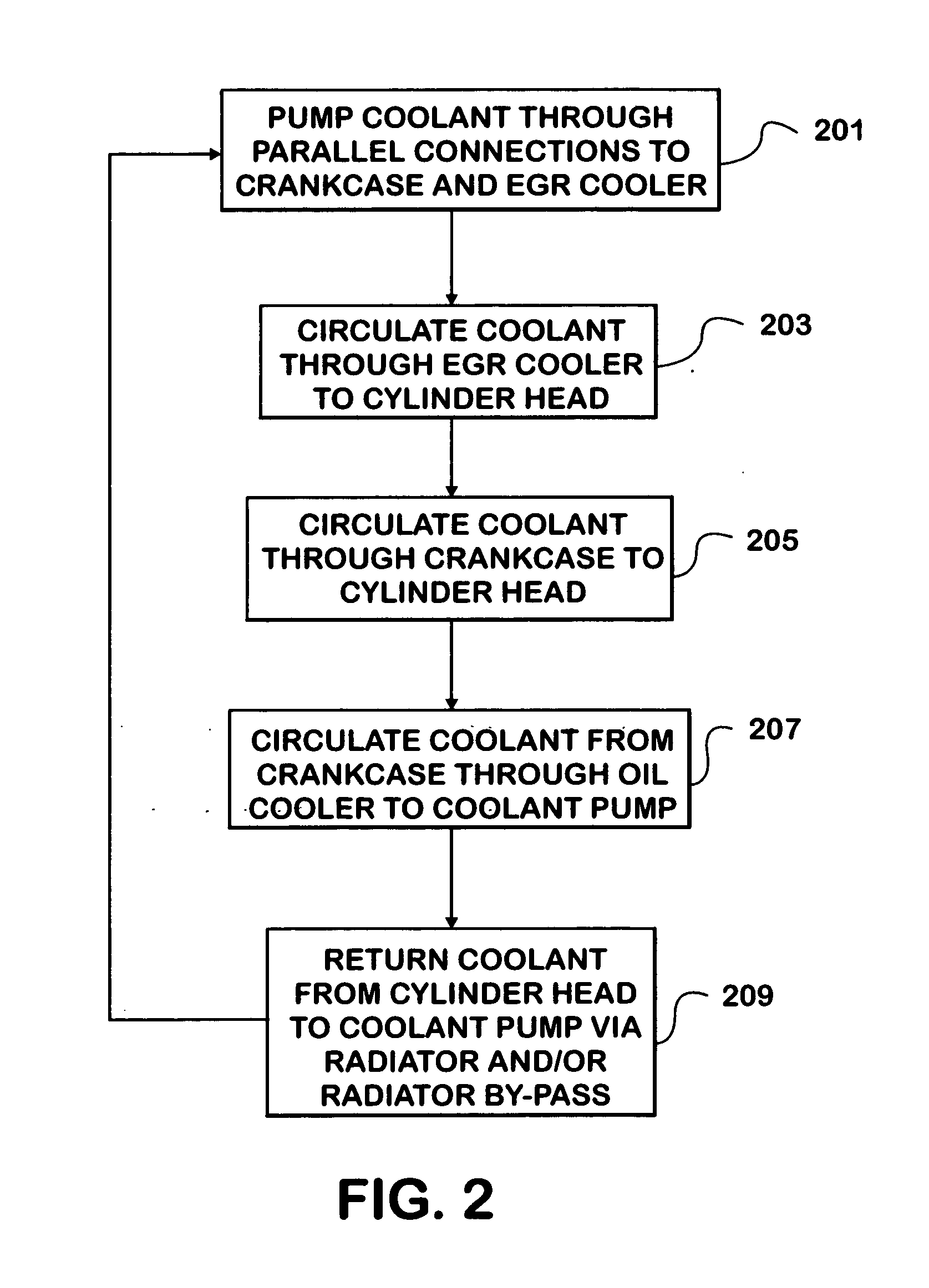
A cooling system pumps coolant through parallel connections to a crankcase and an EGR cooler in an internal combustion engine with exhaust gas recirculation (EGR). A crankcase supply conduit connects a coolant pump to a coolant channel formed by the crankcase. The coolant channel is connected to a coolant chamber formed by the cylinder head. An EGR cooler supply conduit connects the EGR cooler to the coolant pump. The EGR cooler is connected to the coolant chamber. Coolant flows from the coolant pump into the crankcase supply conduit and into the EGR cooler supply conduit at essentially the same time and at essentially the same temperature. The coolant circulates from the coolant pump through the coolant channel into the coolant chamber. The coolant circulates from the coolant pump through the EGR cooler into the coolant chamber. The coolant returns to the coolant pump from the coolant chamber in the cylinder head.

Description

FIELD OF THE INVENTION [0001] This invention generally relates to cooling systems in internal combustion engines with exhaust gas recirculation (EGR). More particularly, this invention relates to cooling systems that reduce the temperature of exhaust gases prior to mixing the exhaust gases with intake air in an internal combustion engine. BACKGROUND OF THE INVENTION [0002] Internal combustions engines convert chemical energy from a fuel into mechanical energy. The fuel may be petroleum-based (gasoline or diesel), natural gas, a combination thereof, or the like. Some internal combustion engines, such as gasoline engines, inject an air-fuel mixture into one or more cylinders for ignition by a spark from a spark plug or the like. Other internal combustion engines, such as diesel engines, compress air in the cylinder and then inject fuel into the cylinder for the compressed air to ignite. An internal combustion engine may use a camshaft system, a hydraulically activated electronically c...

Claims


Application Information

Patent Timeline
IPC IPC(8): F01P3/00F01P5/10F02M25/07
CPCF01P3/02F01P5/10Y02T10/121F02M25/0731F01P2060/04F02M26/28
Inventor OBIDI, T. YOMI
Owner INT ENGINE INTPROP CO LLC
Learn More