Motor control apparatus having current supply phase correction

a technology of motor control and current supply, which is applied in the direction of motor/generator/converter stoppers, electric/dynamo-electric converter starters, peptides, etc., can solve the problems of rotor not being driven normally or being rendered out of control, affecting the shift position of an automatic transmission of a vehicle, and difficulty in stopping the rotor correctly at the target position. , to achieve the effect of increasing both the rotor rotation speed

Active Publication Date: 2006-01-12
TOYOTA MOTORS KABISHIKI KAISHA 50
View PDF23 Cites 19 Cited by
  • Summary
  • Abstract
  • Description
  • Claims
  • Application Information

AI Technical Summary

Benefits of technology

[0009] It is a first object of the present invention to provide a motor control apparatus which can stop the rotor correctly at a target position at the end of a feedback control even if the rotor rotation speed in the feedback control is set high, and which can increase both of the rotor rotation speed in a feedback control and the rotor stop position accuracy.

Problems solved by technology

However, if the rotor rotation speed in a feedback control is increased, because of its inertia the rotor tends to overshoot a target position after the end of the feedback control: it is difficult to stop the rotor correctly at the target position.
Further, in a system that performs a feedback control for rotating the rotor to a target position on the basis of the encoder count, a failure of the feedback control system or an abnormality (e.g., noise, loss of a pulse, or a disconnection of a signal line) in output pulses of the encoder may cause loss of synchronization between the current supply phase (i.e., encoder count) and the rotation phase of the rotor, which may lead to a situation that the rotor cannot be driven normally or is rendered out of control.
As a result, the shift position of an automatic transmission of a vehicle may be determined erroneously during the fail-safe control.

Method used


Image

  • Motor control apparatus having current supply phase correction
  • Motor control apparatus having current supply phase correction
  • Motor control apparatus having current supply phase correction

Examples


first embodiment

[0047] A first embodiment in which the present invention is applied to a position switching device of an automatic transmission of a vehicle will be described in detail.

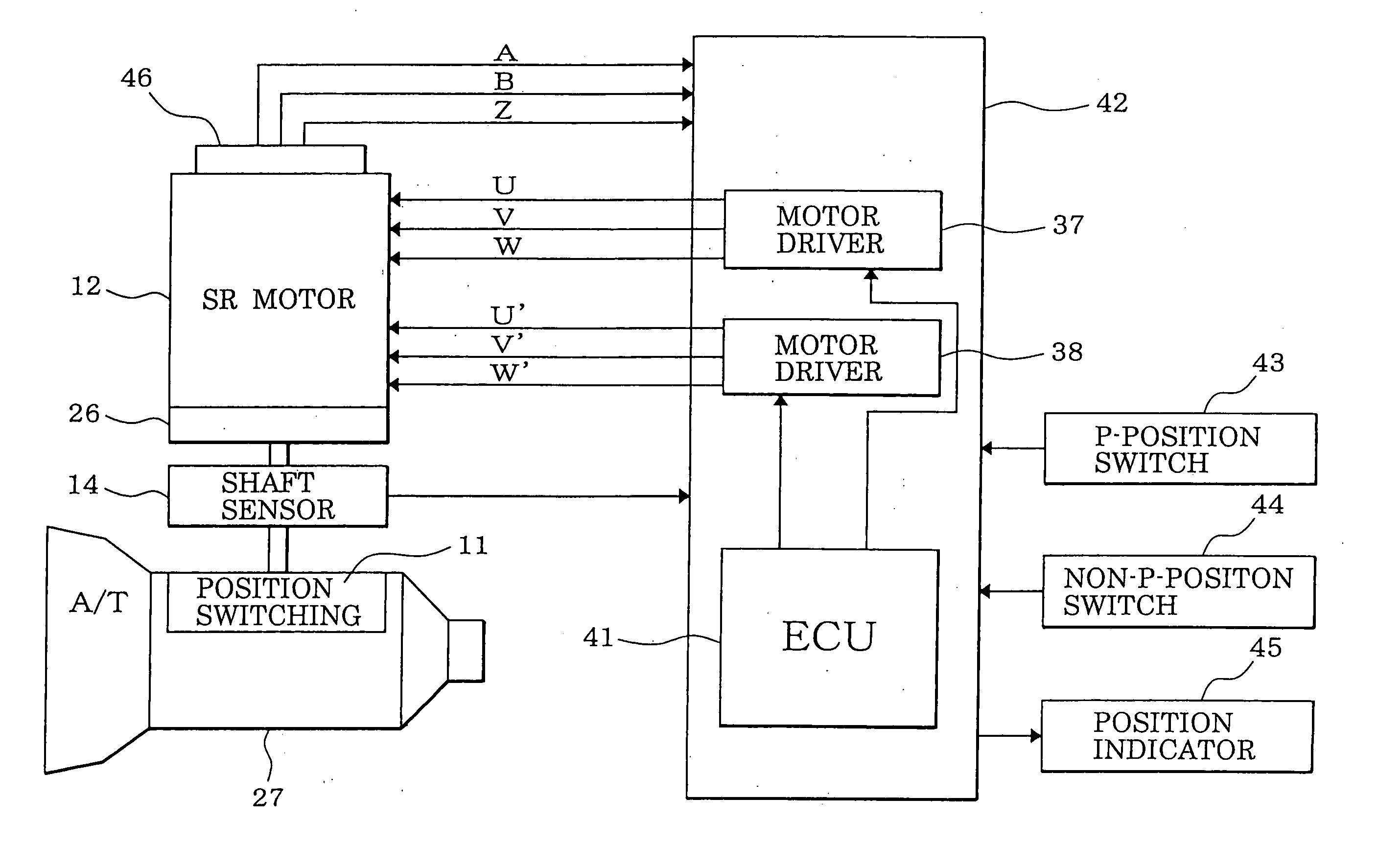
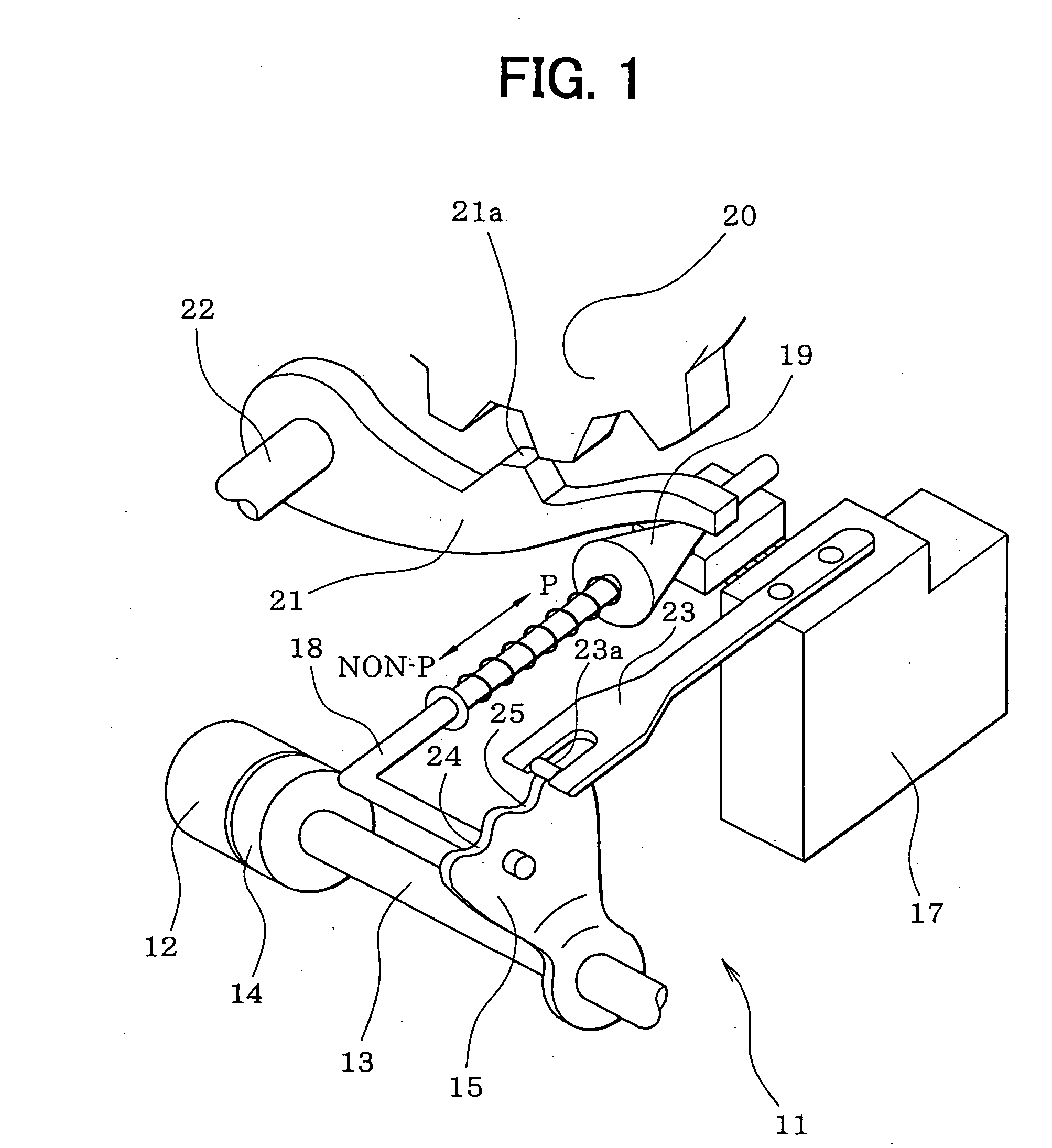
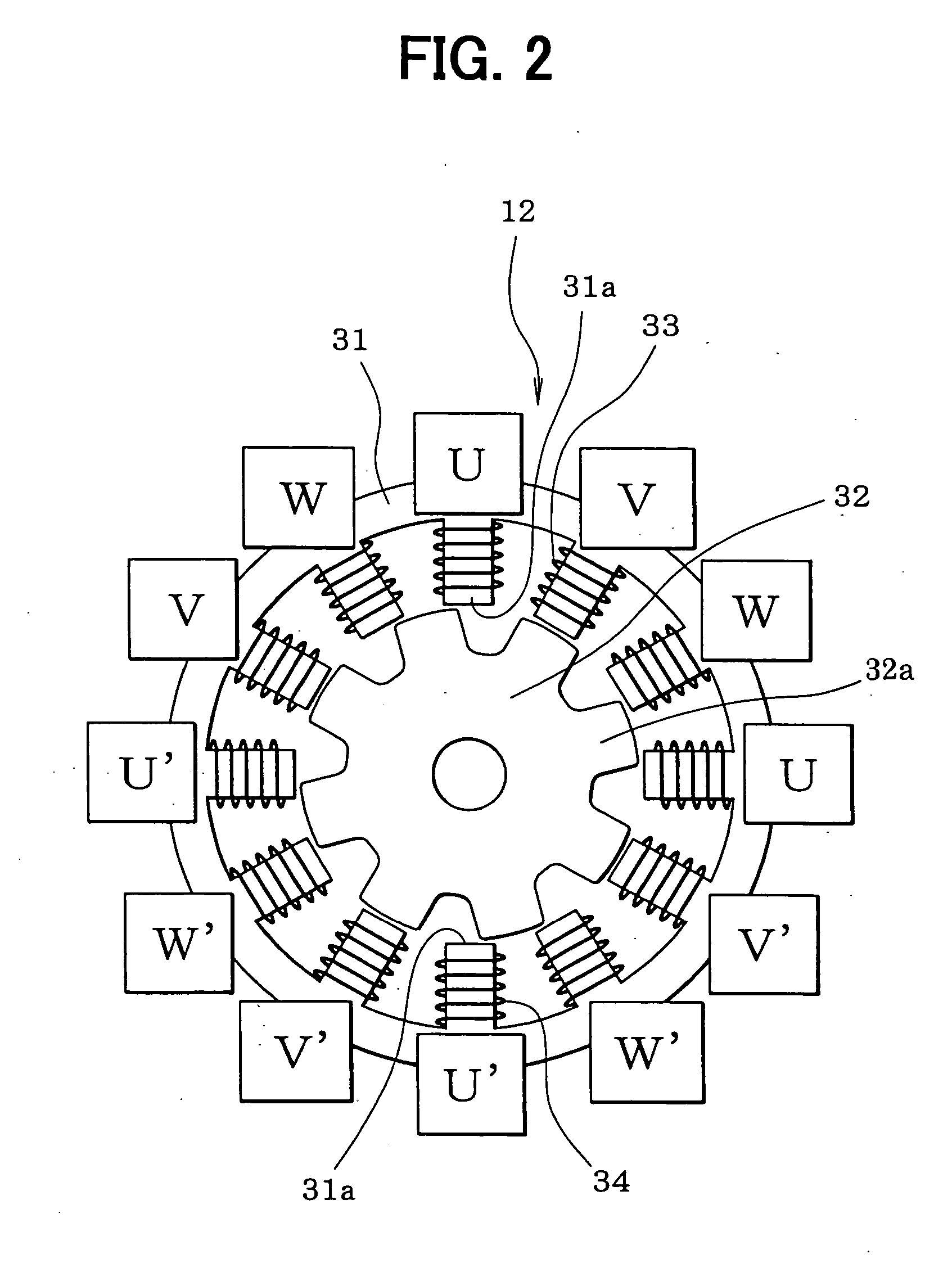
[0048] Referring first to FIG. 1, a position switching mechanism 11 is indicated with numeral 11. A motor 12 as a drive source of the position switching mechanism 11 is a switched reluctance motor, for example, incorporates a speed reducing mechanism 26 (FIG. 4), and is equipped with an output shaft sensor 14 for detecting a rotation position of an output shaft 13 of the speed reducing mechanism 26. A detent lever 15 is fixed to the output shaft 13.

[0049] An L-shaped parking rod 18 is fixed to the detent lever 15. A conical body 19 that is provided at the tip of the parking rod 18 is in contact with a lock lever 21. The lock lever 21 is moved in the vertical direction in accordance with the position of the conical body 19 and thereby locks or unlocks a parking gear 20. The parking gear 20 is attached to the output ...

second embodiment

[0164] In the first embodiment, the rotation amount (of the rotor 32 (i.e., the rotor rotation angle) is converted into the manipulated variable of the position switching mechanism 11 (i.e., the slide length of the parking rod 18) via the rotation transmission system consisting of the speed reducing mechanism 26, the output shaft 13, the detent lever 15, etc. Play exists between the parts constituting the rotation transmission system. For example, backlash exists between the gears of the speed reducing mechanism 26. In a structure in which a connecting portion having a non-circular cross-section that is formed at the tip of the rotary shaft of the motor 12 is fitted into a fitting hole of the output shaft 13, a certain clearance is needed to facilitate the work of fitting the former into the latter.

[0165] Further, as shown in FIG. 27, when the engaging portion 23a of the detent spring 23 moves into the P-position holding recess 24 or the non-P-position holding recess 25 of the dete...

third embodiment

[0210] Next, a motor control according to a third embodiment of the invention will be described by using routines shown in FIGS. 33-35.

[Motor Control]

[0211] A motor control routine shown in FIG. 33 is executed in a prescribed cycle during an ignition switch on period. Upon activation of this routine, it is determined at step 3601 whether a feedback control execution condition is satisfied. The feedback control execution condition is satisfied if, for example, both of the following conditions (1) and (2) are met: [0212] (1) an initial drive has finished (i.e., learning of an initial positional deviation learned value Gcnt has finished. [0213] (2) no system failure or abnormality in output pulses of the encoder 46 (e.g., noise, loss of a pulse, a signal line disconnection) is detected.

[0214] If both of the two conditions (1) and (2) are met, the feedback control execution condition is satisfied and the routine proceeds to step 3602, where a feedback control is performed. In the fee...


PUM

PropertyMeasurementUnit
rotation angleaaaaaaaaaa
mechanical angleaaaaaaaaaa

Abstract

In a motor-driven shift position switching device, when the difference between a target position and the rotation position of a rotor has become smaller than a prescribed value in a motor feedback control, a transition is made to a deceleration control. A phase lead correction amount for correcting the phase lead of the current supply phase with respect to the rotor rotation phase is set in accordance with the rotor rotation speed. Thus, proper braking force suitable for the rotor rotation speed is exerted on the rotor and the rotor can be decelerated smoothly as it approaches the target position. Further, in the period when the current supply to the motor is kept off, the shift position switching determination ranges are set wider than in the period when the current supply to the motor is on.

Description

CROSS REFERENCE TO RELATED APPLICATION [0001] This application is based on and incorporates herein by reference Japanese Patent Applications No. 2002-293271 filed on Oct. 7, 2002 and No. 2002-362617 filed on Dec. 13, 2002. FIELD OF THE INVENTION [0002] The present invention relates to a motor control apparatus for rotationally driving (rotating) the rotor of a motor to a target position by detecting the rotation position of the rotor on the basis of the count of a pulse signal of an encoder and sequentially switching the current supply phase of the motor. In particular, the invention relates to a position switching controller for switching the manipulated position of a position switching mechanism to a target position by driving the position switching mechanism with a motor. BACKGROUND OF THE INVENTION [0003] Brushless motors such as switched reluctance motors are increasingly demanded because they are inexpensive and simple in structure. Those motors incorporate an encoder for outp...

Claims


Application Information

Patent Timeline
Patent Type & Authority Applications(United States)
IPC IPC(8): H02P3/18A61K38/00C07K16/32C12P21/08G01N33/574
CPCH02P6/24H02P5/74H02P6/145F16H2061/326H02P2209/01F16H59/105F16H61/32H02P25/082H02P6/153H02P25/0925
Inventor NAKAI, YASUHIROKAMIO, SHIGERUAMAMIYA, SUMIKOKAWAGUCHI, KAZUOINOUE, YUJI
Owner TOYOTA MOTORS KABISHIKI KAISHA 50
Why Eureka
Try Eureka