Novel Algorithm, Method and apparatus for In-Service Testing of Passive Optical Networks (PON) and Fiber to the Premise (FTTP) Networks

a technology of in-service testing and optical networks, applied in the direction of instruments, electromagnetic transmission, transmission, etc., can solve the problems of inability to observe and resolve multiple reflections, inability to locate impairments on the optical line under test, and current techniques are ineffectiv

Inactive Publication Date: 2006-01-12
WELLER WHITNEY TURREL
View PDF2 Cites 56 Cited by
  • Summary
  • Abstract
  • Description
  • Claims
  • Application Information

AI Technical Summary

Benefits of technology

[0015] This disclosure document outlines a unique and novel application of a custom means for characterization, testing and analysis of test results. The method disclosed hereuses a Optical Time Domain Reflectometer tuned to an “algorithm defined” wavelength. The system retains the baseline measurements for feeder networks or has the baseline measurements downloaded from a service provider support system. The Optical Test Node (OTN) and compares current results with historical results. This novel invention tests the Optical Distribution Network ODN at a wavelength that is unique. This method employs the current practice of basic concept of reflection delay of a test signal propagated through a fiber, or set of fibers. The current technology uses a broad spectrum pulses and wavelengths from 450 nm to 1650 nm sweep to generate a return loss profile of a fiber under test. The current test solutions can only be used when the network is out of service or pieces of the network fiber feeders and legs are physically disconnected from the network. The novel approach contained herein allows testing of feeder and branch networks. (described by ITU G983.1) Current techniques are unable to observe and resolve multiple reflections and locate impairments on the optical line under test. The novel characteristics of the present invention allow testing of the FTTP topology without damage to the sensitive transmission terminal equipment, is solved by the correct selection of a test frequency for the OTDR by the novel FTTP Test Algorithm contained herein. The combination of the ability to test in the presence of live traffic and the use of custom software for the resolution and autocorrelation of incoming reflective echoes with historical data comprises a novel and unique solution for testing and fault location of optical impairments on an ODN.
[0017] Propagation Delays in Optical Fibers—The delay in time between launch of test pulses and the return of energy, reflected from fiber anomalies, at the insertion point (time of flight) is directly related to the length of fiber traveled by the pulse. The exact location of abnormalities on the fiber run such as breaks, kinks or terminations. This direct correlation between time delay and location of elements along the fiber run allows for precise testing of fiber networks through the use of OTDR technologies.

Problems solved by technology

The current test solutions can only be used when the network is out of service or pieces of the network fiber feeders and legs are physically disconnected from the network.
(described by ITU G983.1) Current techniques are unable to observe and resolve multiple reflections and locate impairments on the optical line under test.

Method used


Image

  • Novel Algorithm, Method and apparatus for In-Service Testing of Passive Optical Networks (PON) and Fiber to the Premise (FTTP) Networks
  • Novel Algorithm, Method and apparatus for In-Service Testing of Passive Optical Networks (PON) and Fiber to the Premise (FTTP) Networks
  • Novel Algorithm, Method and apparatus for In-Service Testing of Passive Optical Networks (PON) and Fiber to the Premise (FTTP) Networks

Examples


case 1 exists

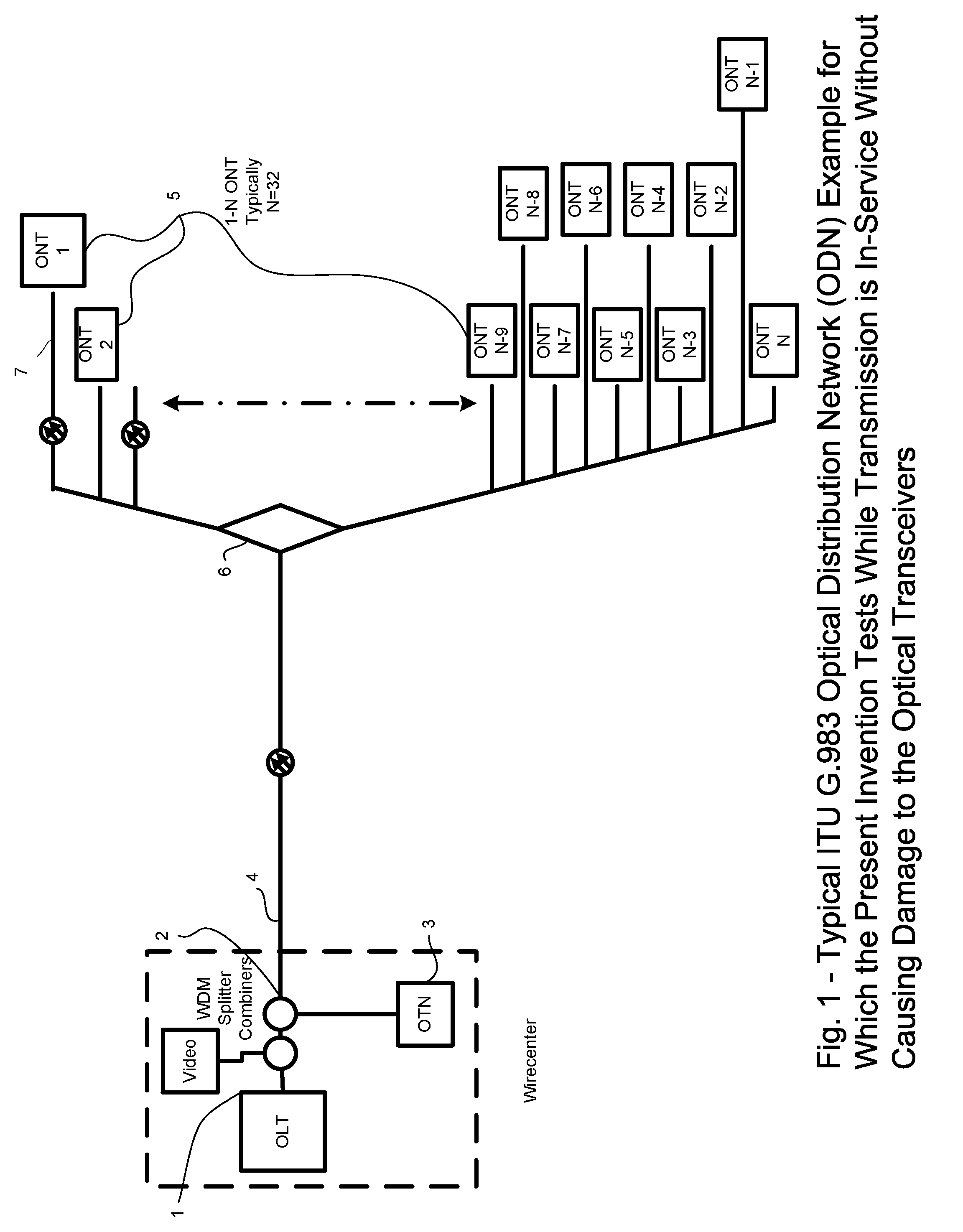
[0036] If Case 1 exists and plurality of reflections are apparent at the OTN receiver (20) advanced techniques of the present invention will be used to isolate the fault. A combination of resonance stimulation of the optical fiber and a short duty cycle will give us the ability to get enough energy in the fiber to spot problems by windowing in on expected reflections and lack of reflections to identify if the plant is responding as expected. An example of OTN OTDR information returned in the presence of working traffic and without damage to the ONT and OLT devices is presented in FIG. 4. (28,29,30)

[0037] If the plant has a reflective, such as, but not limited to, a fiber break condition that impairs light transmission a fault will be flagged located and identified using techniques familiar to those skilled in the OTDR technology.

[0038] As a result of the enhanced reflectivity of a fiber break, the OTDR will calculate the distance to fault and the OTN will report the position to the...

case 1

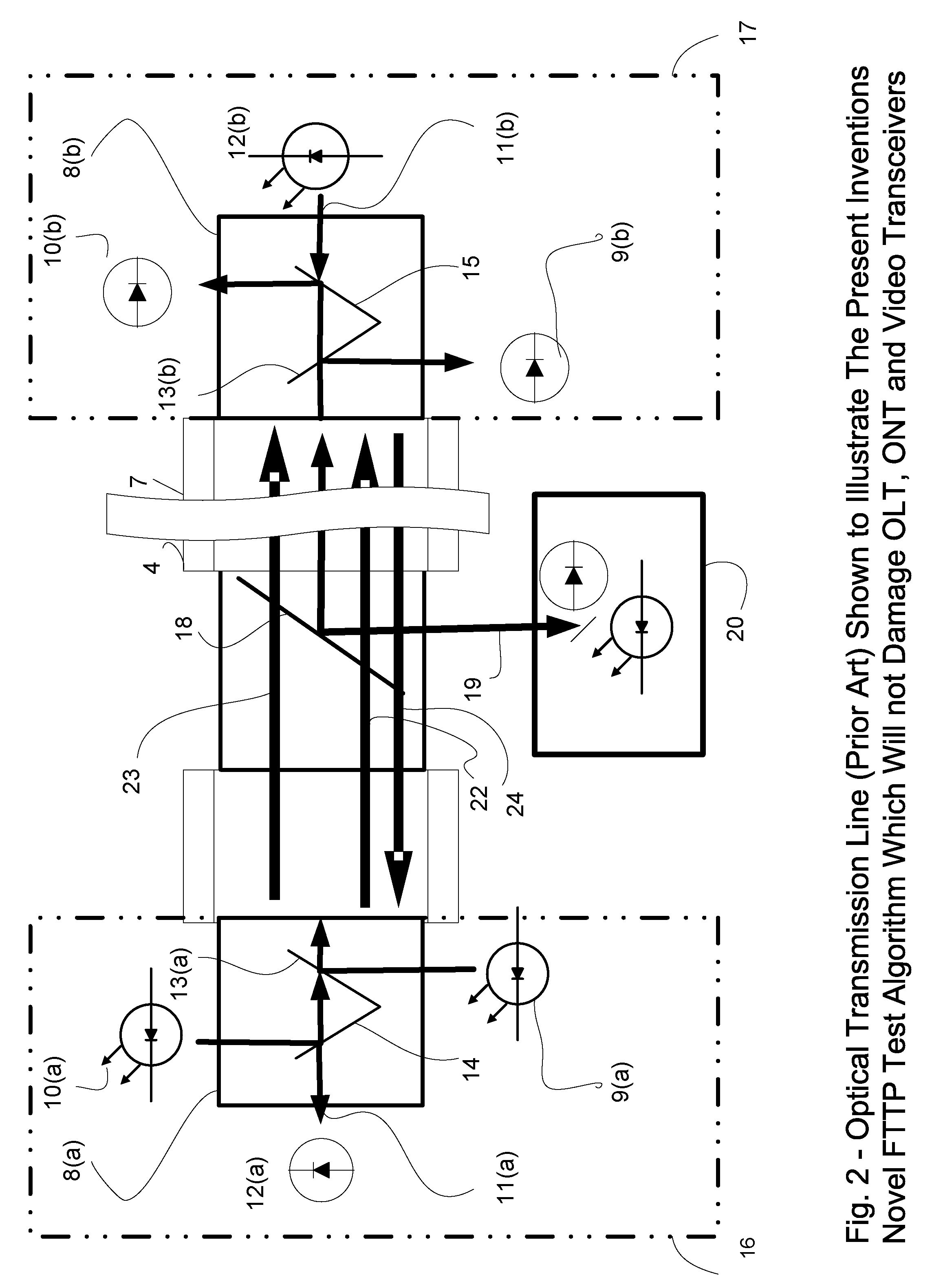
[0043] Case 1) The pulse is reflected by the band-pass filter rejection from the triplexer transceiver is such that the return loss (27) is very low:

[0044] a. The apparatus invention uses the topology map of the optical circuit to calculate the time of flight (TOF) for the round trip pulse for each leg based on an expected reflection TOF calculated from the record of the feeder and legs. Where Cmedia represents the speed of light in the media of transmission. In this case the media would be Silica.

TOF=(Distance of feeder+Distance of leg) / Cmedia

[0045] b. Attenuation is estimated based on loss for the feeder and each leg.

[0046] c. The transmission line is stimulated with a test signal which is modulated to optimize the energy density of the reflected pulse returning to the splitter / coupler port for the specific leg in test.

[0047] d. Sweeping modulation causes pulse density to vary. At specific pulse train or sign wave frequencies each leg in turn will experience first order (2nd or...

case 2

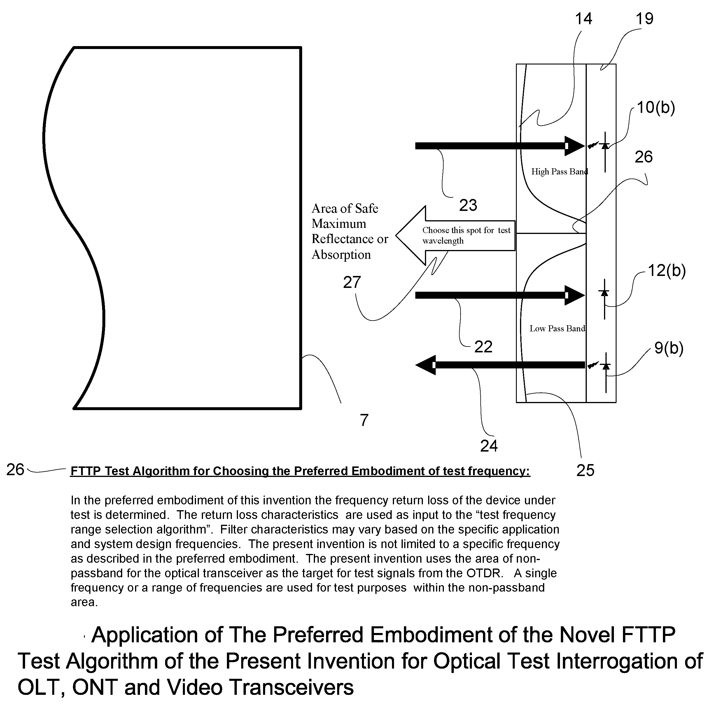
[0052] Case 2) The optical pulse is completely absorbed by the transceiver module such that the return loss in the optical range used for testing is high enough so that end reflections are not detectable from the test apparatus.

[0053] a. Choice of the center optical frequency at the point of maximum filter rejection for the triplexer of diplexer transceiver attached to the end of each leg means that the sensitive receivers will not be affected by the optical interrogation of the attached OTDR test apparatus.

[0054] b. In this case at the frequencies specified noreflections will be seen on the OTDR read out. This condition indicates a healthy network and the test can be done using the present invention, the novel FTTP Test Algorithm to choose the interrogation optical frequency and a modified OTDR, testing is accomplished without harm or interruption of service to the ONT and customer respectively.

[0055] c. Using the present invention as in Case 2 item b, if a reflection is detected...


PUM

PropertyMeasurementUnit
wavelengthaaaaaaaaaa
wavelengthsaaaaaaaaaa

Abstract

Locating a fault of an optical transmission line in a system which performs bidirectional optical communication between a wire center Optical Line Terminal (OLT) and plural subscriber devices, Optical Network Terminal (ONT). In this ITU defined topology, a feeder extending from the OLT is branched by a passive (non powered) splitter / coupler device into plural legs each connected to the ONT devices. The present invention encompasses a novel test apparatus and technique for fault location on Passive Optical Networks (PON) and / or Fiber of the premise Networks (FTTP), encompassing APON, BPON and EPON allowing non-service interruptive test, without damage to the ONT or OLT transceivers. The invention provides service providers the ability to locate a fault occurring on an optical transmission line while the system is actively performing bidirectional optical communication between a OLT / head-end device and plurality of ONT / subscriber devices.

Description

CROSS REFERENCE TO RELATED APPLICATIONS [0001] U.S. Pat. No 5,187,362 February, 1993 Keeble 250 / 227. U.S. Pat. No. 6,028,661 February 2000 Minami et al. 356 / 73. Foreign Patent Documents 9-152386 June 1997 JP. 9-329526 December, 1997 JP. 10-239539 September, 1998 JP. USPTO Disclosure Document No. 550769 Apr. 6, 2004 BACKGROUND OF INVENTION [0002] The present invention is an enhancement to current methods for testing the feeder and respective transmission legs using currently available methods. The Optical TestNode (OTN) is a novel apparatus which incorporates a novel FTTP Test Algorithm, the OTN emits an optical test signal, observes a reflected signal. The test signal, whose optical frequency is chosen using the novel FTTP Test Algorithm, results in the test signal operating in an optical band that is not normally used for in-service data transmission or testing, and is contained within the optical spectrum of the ITU G.983 architecture. As a result of this novel choice of frequency...

Claims


Application Information

Patent Timeline
Patent Type & Authority Applications(United States)
IPC IPC(8): G01N21/00
CPCH04B10/0771H04B10/071
Inventor WELLER, WHITNEY TURREL
Owner WELLER WHITNEY TURREL
Why Eureka
Try Eureka