
Optical pickup device, recorder and/or reproducer

a pickup device and optical technology, applied in the optical field, can solve the problems of increasing the number of components of the optical system, insufficient light on the signal recording surface of the disc, and complicated construction, and achieve the effect of maximizing the optical path

Inactive Publication Date: 2006-01-12
SONY CORP
View PDF10 Cites 36 Cited by
  • Summary
  • Abstract
  • Description
  • Claims
  • Application Information

AI Technical Summary

Benefits of technology

[0015] Accordingly, it is desirable to provide an optical pickup device which realizes an optical system having an optical magnification suitable for each disc format between three optical discs and a light emitting means for emitting a laser beam having a wavelength corresponding to each disc in the optical system of the optical pickup for recording and / or reproducing an information signal to the optical discs and which prevents the number of components from being increased to simplify the composition of the optical system, thereby preventing the length of an optical path from being lengthened, the optical pickup from being increased in size.
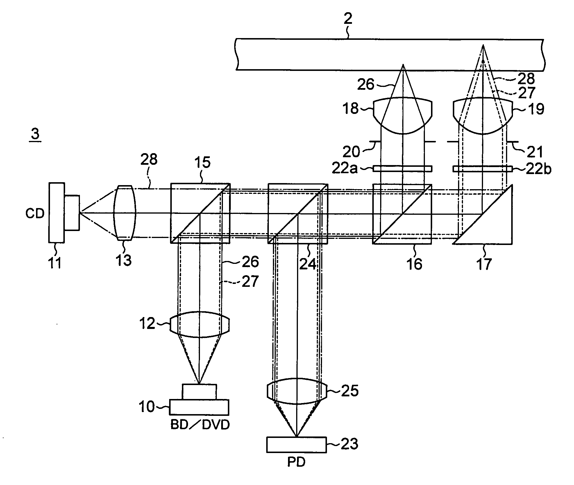
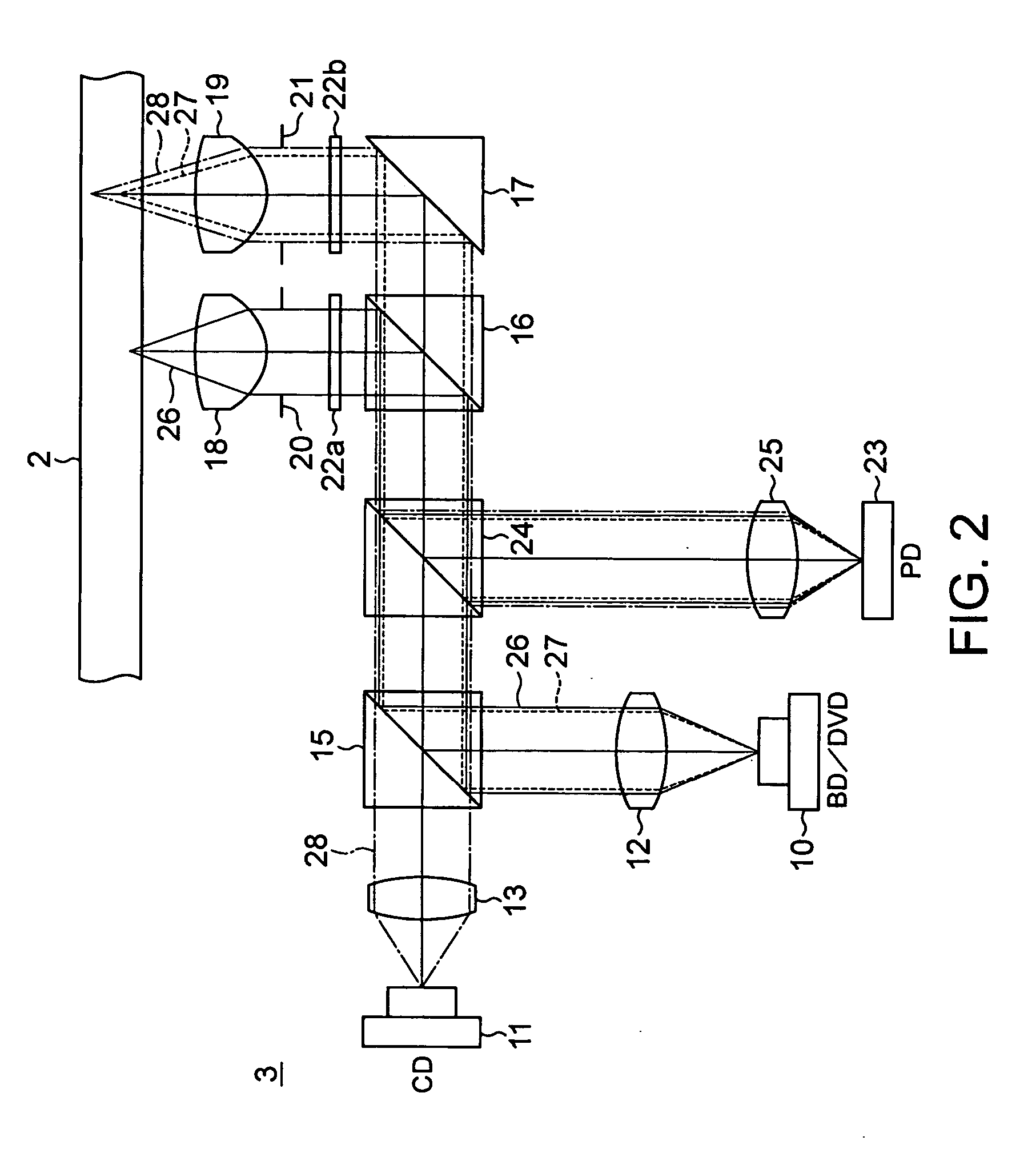
[0019] According to the optical pickup device and the recorder and / or reproducer, the optical path having optimum magnifications to the first to the third laser beams emitted corresponding to the three optical discs having different formats can be formed by using the two light emitting units and the collimator lenses and two objective lenses. Therefore, the optical paths corresponding to the laser beams of the respective wavelengths can be commonly used, and the optical system having the optical magnifications suitable for the respective optical disc formats can be realized between the light emitting units for emitting the laser beam having the wavelengths corresponding to the respective optical discs and the respective optical discs without introducing the maximizing of the optical path of the pickup optical system.

Problems solved by technology

As a result, the quantity of light on the signal recording surface of the disc becomes insufficient.
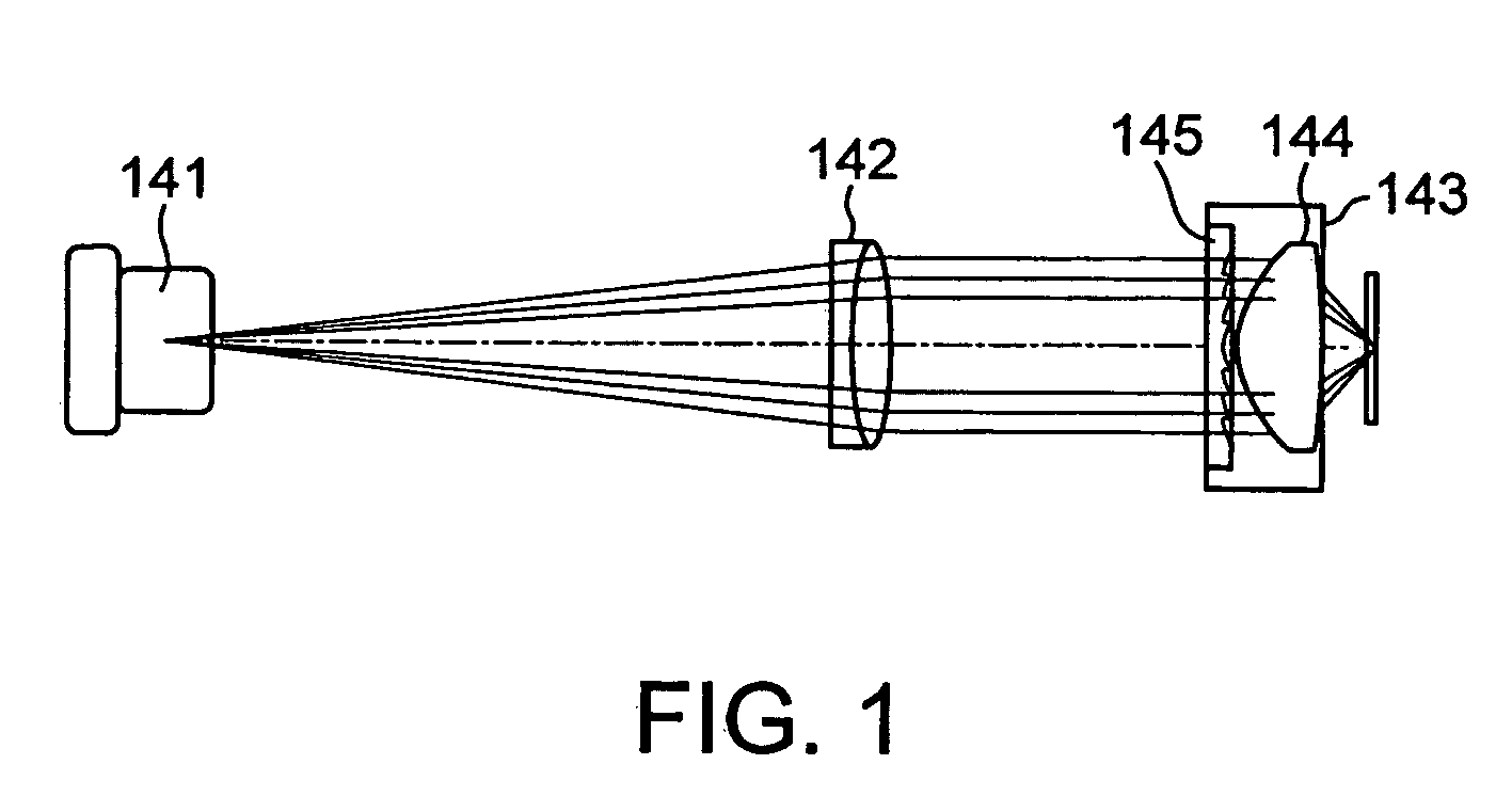
Accordingly, when one lens system for realizing the optical magnification suitable for the three disc formats is composed, the number of components for constituting the optical system is increased, and its construction is complicated.
Therefore, this optical system cannot respond to the requests of shortening the optical path of the pickup optical system and a size reduction of the pickup device, etc.

Method used


Image

  • Optical pickup device, recorder and/or reproducer
  • Optical pickup device, recorder and/or reproducer
  • Optical pickup device, recorder and/or reproducer

Examples


first embodiment

[0069] Then, an embodiment of an optical pickup device 1 according to the present invention will be described. The optical pickup device 1 comprises, as shown in FIG. 5, a pickup base 53 supported by a pair of guide shafts 51, 52 arranged in a radial direction of the optical disc 2, and an optical system 54 formed in this pickup base 53. The optical system 54 comprises: a 2-wavelength laser diode 55 for emitting a laser beam having a wavelength of 405 nm corresponding to a BD and a laser beam having a wavelength of 660 nm corresponding to a DVD; a 1-wavelength laser diode 56 for emitting a laser beam having a wavelength of 780 nm corresponding to a CD; a second polarization beam splitters 57, 58 each having a wavelength selectivity; a collimator lens 59 supported movably in the optical axis direction of the laser beam; a beam splitter 60 for reflecting the laser beam having the wavelength of 405 nm to the optical disc 2 side and transmitting the laser beams having the wavelengths of...

second embodiment

[0084] Next, another embodiment of the optical pickup device 1 according to the present invention will be described. This optical pickup device 1 constitutes an optical system 80 by using a 2-wavelength semiconductor laser for emitting a laser beam having a wavelength of 660 nm and a laser beam having a wavelength of 780 nm, and a so-called laser coupler obtained by integrating, in a hybrid manner, photodetectors for receiving the reflected light from the optical disc 2 of these laser beams. As shown in FIG. 6, the optical pickup device 1 comprises a pickup base 83 supported by a pair of guide shafts 81, 82 arranged in a radial direction of the optical disc 2, and the optical system 80 is formed in the pickup base 83. The optical system 80 comprises: a 1-wavelength laser diode 85 for emitting the laser beam having the wavelength of 405 nm corresponding to the BD; a laser coupler 86 mounted with a receiving and emitting element of the laser beam having the wavelength of 780 nm corres...


PUM

PropertyMeasurementUnit
wavelengthaaaaaaaaaa

Abstract

The present invention provides an optical pickup device which realizes an optical system having an optical magnification suitable for each disc format between three optical discs and a light emitting means for emitting a laser beam having a wavelength corresponding to each disc in the optical system of the optical pickup for recording and / or reproducing an information signal to the optical discs and which prevents the number of components from being increased to simplify the composition of the optical system, thereby preventing the length of an optical path from being lengthened, the optical pickup from being increased in size. The optical pickup device has a first light emitting unit for emitting a laser beam having a first wavelength and a laser beam having a second wavelength, a second light emitting unit for emitting a laser beam having a third wavelength, a first collimator lens for transmitting the laser beam having the first wavelength and the laser beam having the second wavelength, a second collimator lens for transmitting the laser beam having the third wavelength, a first objective lens for transmitting the laser beam having the first wavelength transmitted through the first collimating lens or the laser beam having the third wavelength transmitted through the second collimator lens, and a second objective lens for transmitting the laser beam having the second wavelength transmitted through the first collimator lens.

Description

CROSS REFERENCES TO RELATED APPLICATIONS [0001] The present invention contains subject matter related to Japanese Patent Application JP 2004-203814 filed in the Japanese Patent Office on Jul. 9, 2004, the entire contents of which being incorporated herein by reference. BACKGROUND OF THE INVENTION [0002] 1. Field of the Invention [0003] The present invention relates to an optical pickup device corresponding to an optical disc of at least three formats. The present invention particularly relates to an optical pickup device having a 2-wavelength laser element and a 1-wavelength laser element, and a collimating means having different refractive powers of two systems and an objective lens having two different focal lengths, and a recorder and / or reproducer using the same. [0004] 2. Description of Related Art [0005] There is, heretofore, an optical pickup device for recording and / or reproducing an information signal to an optical disc having different formats, such as a CD (Compact Disc) ...

Claims


Application Information

Patent Timeline
Patent Type & Authority Applications(United States)
IPC IPC(8): G11B7/00G11B7/123G11B7/1275G11B7/1374G11B7/1392
CPCG11B7/123G11B7/1275G11B2007/0006G11B7/13925G11B7/1374G11B7/1376
Inventor NISHI, NORIAKIYAMAMOTO, KENJIKOBAYASHI, TAKASHISHINDO, KATSUHIROKOBAYASHI, YUHEI
Owner SONY CORP
Learn More