Transmitter stage

a technology of transceiver and output signal, applied in the direction of transmission/receiver shaping network, modulated carrier system, transmission, etc., can solve the problem of linear amplifier efficiency, the efficiency of linear amplifiers, compared with nonlinear power amplifiers, which achieve an efficiency of about 50% to 60%, and the transmission signal is noticeable and noticeable distortion. problem, to achieve the effect of preventing over-modulation, reducing the bandwidth of the pll loop, and reducing the number of inpu

Inactive Publication Date: 2006-01-12
FRAUNHOFER GESELLSCHAFT ZUR FOERDERUNG DER ANGEWANDTEN FORSCHUNG EV
View PDF13 Cites 10 Cited by
  • Summary
  • Abstract
  • Description
  • Claims
  • Application Information

AI Technical Summary

Benefits of technology

[0045] A further advantage of the present invention is that the shift of the digital interface to the front is shifted up to a preferably provided anti-aliasing filter (AAF), so that a maximum part of the transmitter stage is embodied digitally and may thus be implemented integrated in a digital signal processor.
[0046] With employment of the variable attenuator in the feedback branch, amplitude stabilization of the returned signal is achieved to prevent over-modulation of the analog / digital converter in the feedback branch.
[0047] A further advantage of the present invention is that the I / Q signal of an EDGE or UMSTS signal source is processed in completely digital manner into amplitude information A(t) and phase information φ(t). Thereby, use of limiter circuits and amplitude demodulators like in the polar loop concept becomes superfluous.
[0048] Moreover, the present invention is advantageous in that preferably digital frequency conversion of the phase information is used. Hereby, sufficient adjustment of the bandwidth of the PLL loop is guaranteed. In particular, it is preferred to embody both the loop filter of the PLL and the low-pass filter connected downstream of a variable amplifier in the amplification control means in digital manner, so that simple and flexible adjustment of the filter coefficients of the digital filter is possible to realize arbitrarily desired transfer functions.
[0049] A further advantage of the present invention is that AM / PM distortions of the nonlinear power amplifier are corrected by the PLL.
[0050] Furthermore, the present invention is advantageous in that it provides high precision by employing completely digital signal processing for the substantial parts of the locked loop as well as for the substantial part of the amplification control means for amplitude variation of the power amplifier.

Problems solved by technology

The result is spectral broadening of the output signal after the nonlinear power amplifier and noticeable distortion of the transmission signal, respectively.
This leads to an increase in the bit error rate (BER) at equal reception field strength.
The efficiency of linear amplifiers, in comparison with nonlinear power amplifiers, which achieve an efficiency of about 50% to 60%, is, however, much worse at about 35%.
The high energy consumption of the system by the lower efficiency of the components is in contrast to the desire to achieve as-long-as-possible operation times of the mobile station.
On the other hand, high transmission power is not desired due to increasing resistance among the people.
Furthermore, high transmission power leads to the fact that the cells can only be designed in relatively rough-meshed manner, or that a carrier frequency cannot be “reused” as often as possible in a cell raster in order to allow for a high participant number in the limited frequency band.
Particularly, when using nonlinear amplifiers, high transmission power has the problem that side channel interferences may increase, i.e. that a transmitter actually specified for one carrier frequency also transmits power, due to its non-linearity, in a side channel in which it actually should not be allowed to send at all or only below a threshold.
Furthermore, especially for mobile telephones, there is the requirement that they have to be inexpensive, because the mobile telephone market has become an extremely competitive market, in which already small price advantages have lead to the fact that the one system survived, i.e. was accepted by the market, whereas the other system has not been successful on the market.

Method used


Image

  • Transmitter stage
  • Transmitter stage
  • Transmitter stage

Examples


Embodiment Construction

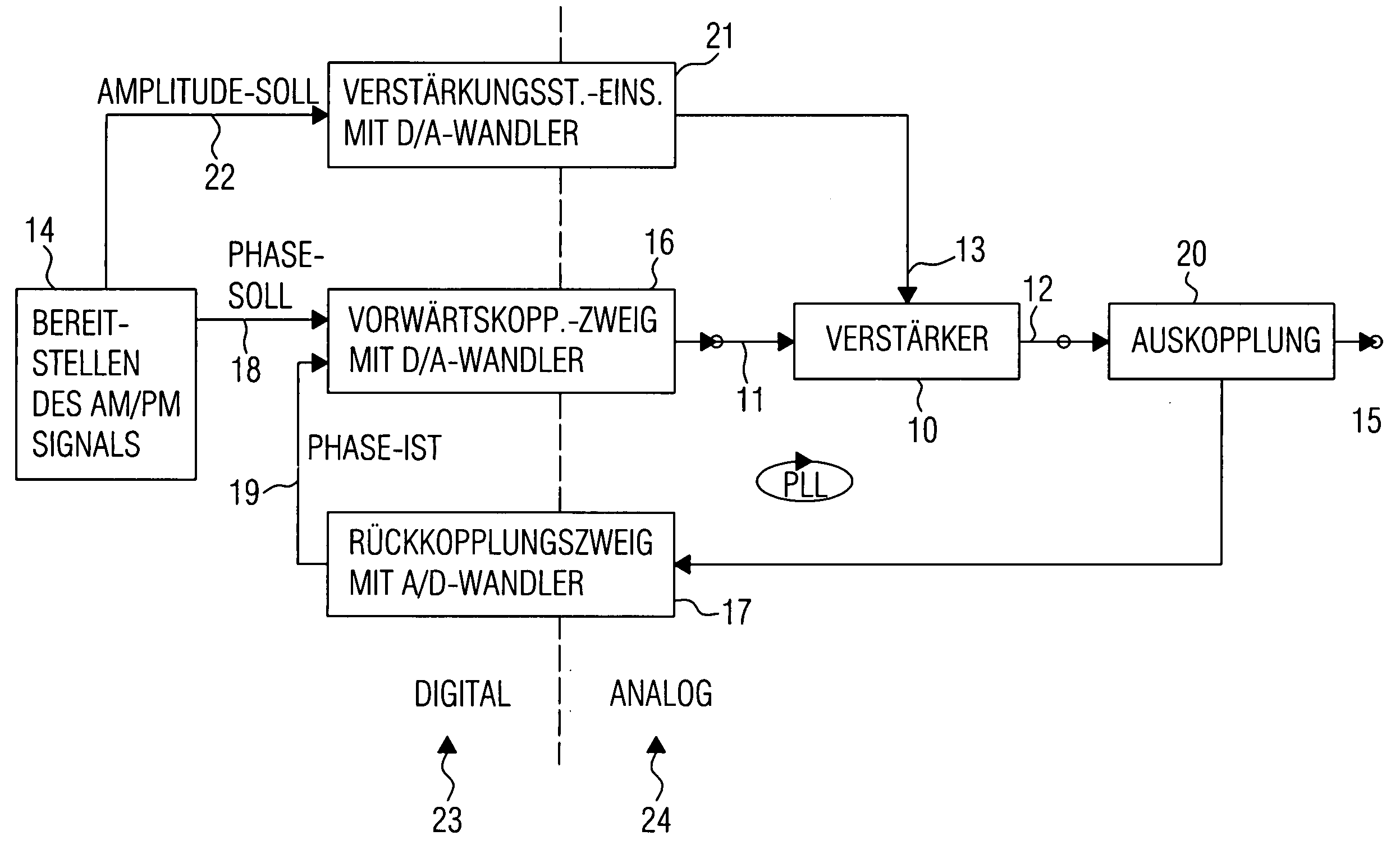
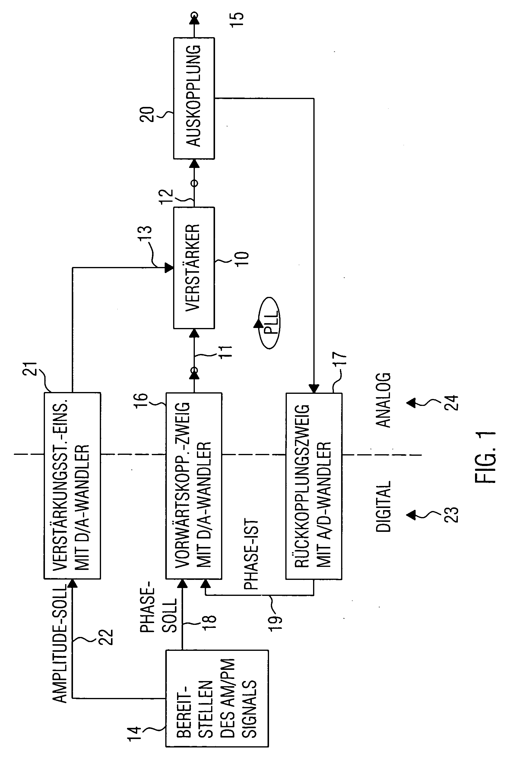
[0058]FIG. 1 shows a block circuit diagram of an inventive transmitter stage for transmitting an amplitude and phase-modulated signal using a power amplifier 10 with a signal input 11, a signal output 12, and an amplification control input 13.

[0059] The transmitter stage includes means 14 for providing the amplitude and phase-modulated signal, which is designated with 14 in FIG. 1. Means 14 is operable to generate the signal, which is finally output from the amplifier 10 and is to be radiated e.g. at an antenna, which can be coupled at an overall output 15 of the circuit.

[0060] The transmitter stage shown in FIG. 1 further includes a phase-locked loop (PLL) with a feed-forward branch 16 and a feedback branch 17. The feed-forward branch 16 includes a phase detector for comparing the phase representation supplied by means 14 as phase target signal 18 with a phase actual signal 19, in order to provide a tuning signal filtered by a loop filter and fed to a controllable oscillator, whi...


PUM


Abstract

A transmitter stage working according to the envelope restoration principle includes means for providing an amplitude representation and a phase representation of an amplitude and phase-modulated signal to be transmitted, as well as a phase-locked loop with a feed-forward branch and a feedback branch, as well as amplification control means formed to convert the amplitude representation to an amplification control signal, which may be fed into the amplification control input of a nonlinear power amplifier. In the feed-forward branch, a digital/analog converter is arranged. Furthermore, in the feedback branch, an analog/digital converter is arranged, so that the phase detector of the phase-locked loop is implemented in digital form. By an as large as possible proportion of digital signal processing, an inexpensively implementable and exactly working transmitter stage is obtained.

Description

CROSS-REFERENCE TO RELATED APPLICATION [0001] This application is a continuation of co-pending International Application No. PCT / EP03 / 12736, filed Nov. 14, 2003, which designated the United States and was not published in English and is incorporated herein by reference in its entirety.BACKGROUND OF THE INVENTION [0002] 1. Field of the Invention [0003] The present invention relates to transmitter stages, and in particular to transmitter stages being able to send a phase and amplitude-modulated signal via an amplifier operated in the nonlinear range, according to the EDGE or UMTS specification. [0004] 2. Description of the Related Art [0005] For mobile communication services, only a limited amount of frequency bands exist. The required channel bandwidth in the data transmission and the possible data rate are critical factors, which characterize the effectiveness of a transmission system. Within a frequency band, a maximum data rate is strived for. There are various methods permitting ...

Claims


Application Information

Patent Timeline
Patent Type & Authority Applications(United States)
IPC IPC(8): H04K1/02H04L27/20H04L27/34
CPCH04L27/34H04L27/2017
Inventor JAFARI, HOUMANBURDENSKI, RALFULBRICHT, GERALD
Owner FRAUNHOFER GESELLSCHAFT ZUR FOERDERUNG DER ANGEWANDTEN FORSCHUNG EV
Why Eureka
Try Eureka