Soldering method and solder alloy for additional supply

Active Publication Date: 2006-01-19
PANASONIC CORP +1
View PDF9 Cites 11 Cited by
  • Summary
  • Abstract
  • Description
  • Claims
  • Application Information

AI Technical Summary

Benefits of technology

[0073] From yet another standpoint, the present invention is a lead free, replenishment solder alloy which contains Sn and Ag and further contains 60-100 ppm by mass of P, the alloy being used to maintain the P content of a solder bath constant while supplying the replenishment solder alloy to the solder bath in a flow soldering method.
[0074] In the present invention, the constituent elements of the solder alloy of a solder bath and the constituent elements of a solder alloy supplied to the solder bath are fundamentally the same except for the oxidation suppressing element, but as stated earlier, in cases in which the content of elements increases during soldering, a solder may be supplied which does not contain any of the elements which increase or which has a smaller content than a prescribed content.
[0075] In a solder alloy for replenishing a solder bath according to the present invention, if the P content is less than 60 ppm, the amount of P which is consumed during wave soldering cannot be replenished and the P content in the bath decreases, and the amount of P in the bath cannot be maintained in a stable state. If it is lar

Problems solved by technology

During soldering operations, various soldering defects such as unsoldered portions, bridges, and voids may occur.
If the dross accumulates in the vicinity of the nozzle, the stability of the molten solder wave is disturbed, a portion of the dross which is entrained in the solder wave adheres to the printed circuit board, and this may lead to soldering defects, so it is necessary to periodically remove dross which accumulates on the surface of the solder bath.
A similar problem with the formation of dross can be seen even when using a stationary solder bath when carrying out soldering at a high temperature in an oxidizing atmosphere, such as when carrying out soldering of urethane coated copper wire.
If a large amount of such dross is produced, the time required for dross removal and the amount of discarded solder increase, so running costs increase.
Therefore, the amount of P, i.e., of an oxidation suppressing element in the solder alloy decreases, and eventually it is completely consumed.
If an oxidation suppressing element in a solder alloy is entirely consumed, the dross

Method used


Image

  • Soldering method and solder alloy for additional supply
  • Soldering method and solder alloy for additional supply

Examples


example 1

[0078] Specific steps in carrying out this example are as follows.

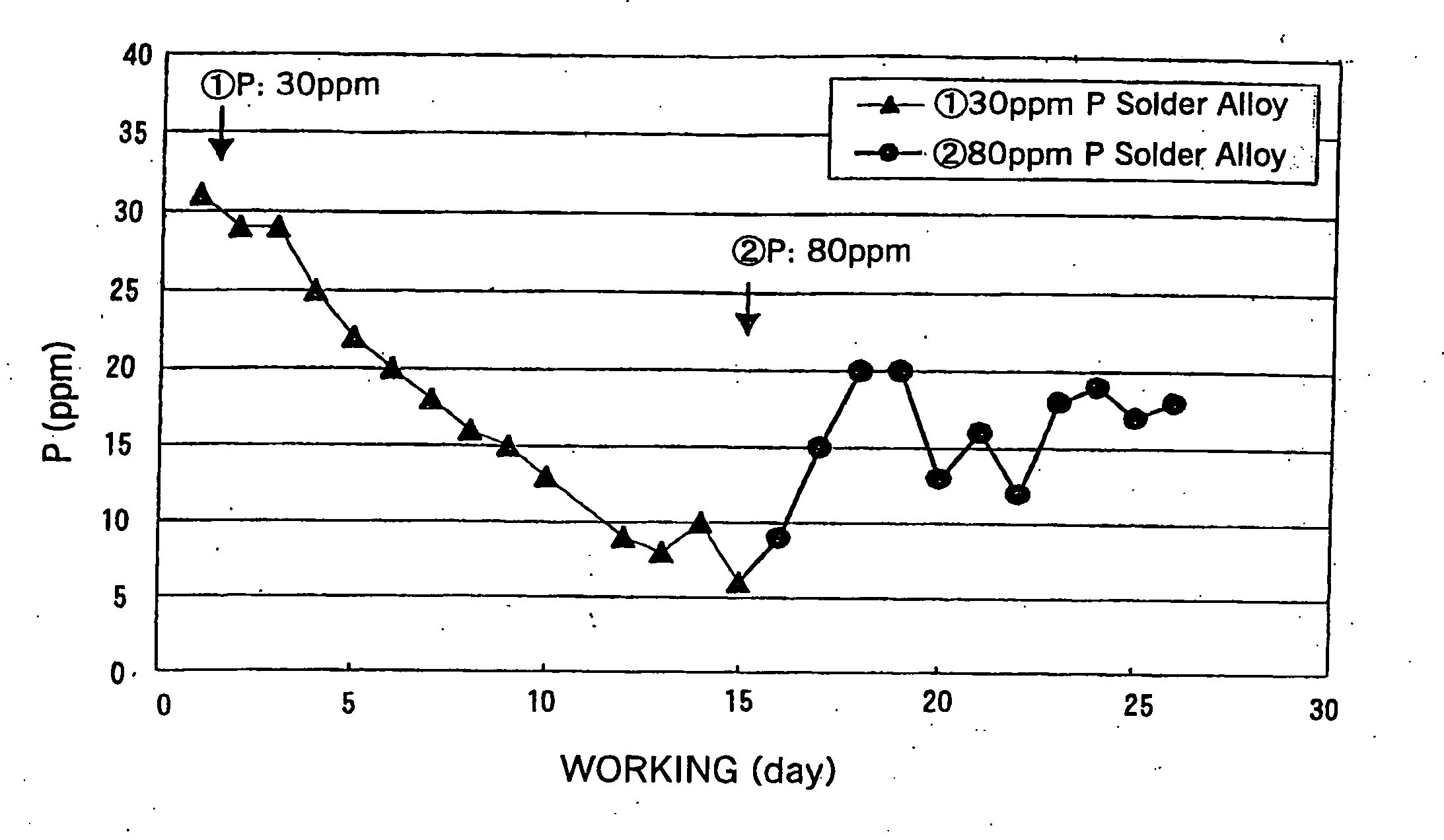
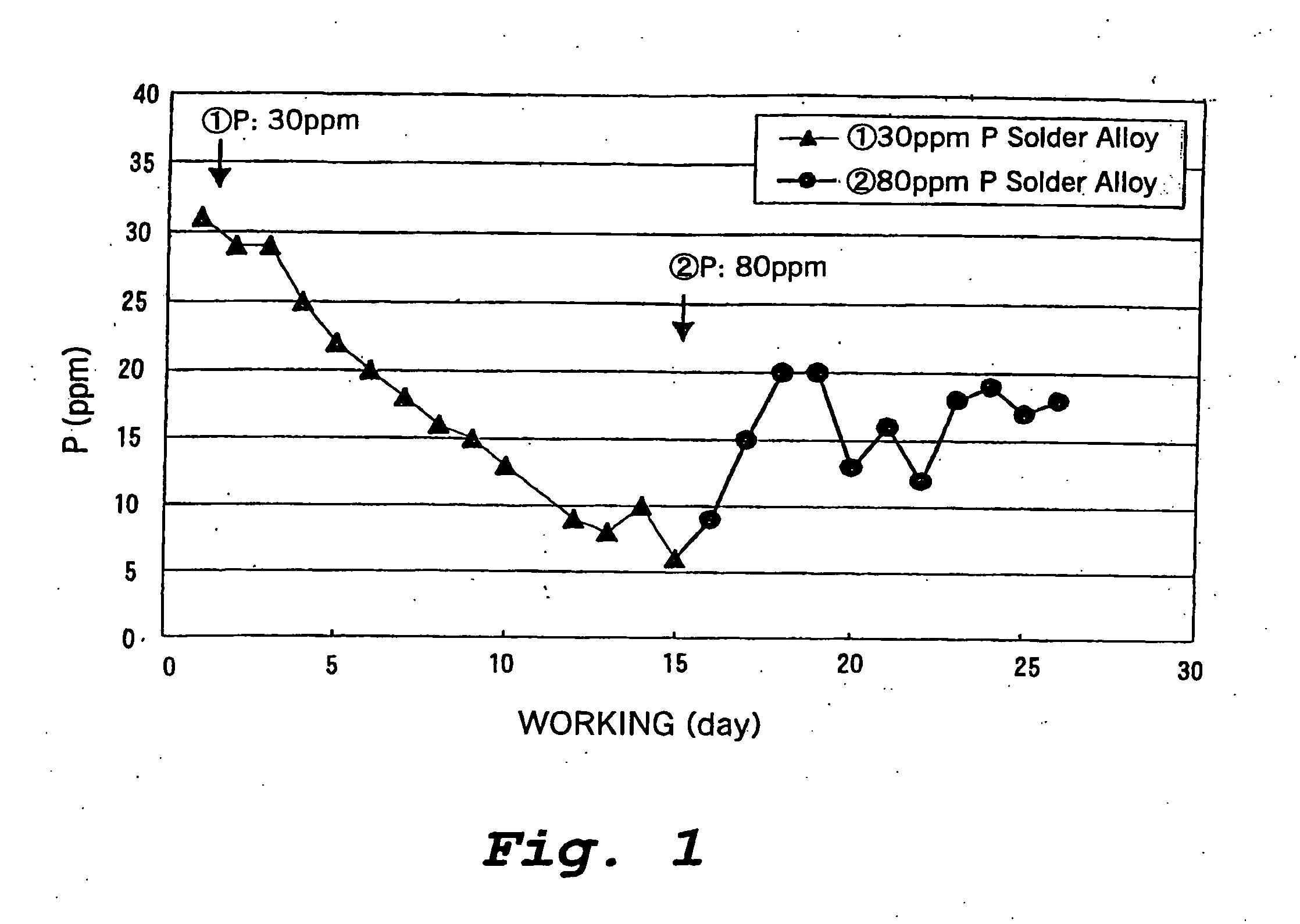
[0079] (1) Sn-3.0Ag-0.5Cu-0.003P solder, which is a P-containing lead free solder alloy suitable for suppressing oxidation of molten solder, was melted to form a solder bath (weight: 330 kg).

[0080] (2) The decrease in the amount of the solder bath in the soldering tank during 12 days of operation, i.e., the replenished amount of the solder alloy and the rate of decrease of the P concentration were determined.

[0081] Total supplied amount of Sn-3.0Ag-0.5Cu-0.003P solder alloy to the solder bath: 220 kg

[0082] Concentration of P in the solder bath after 12 days of operation: 0%

[0083] (3) The average decrease per day in the amount of the oxidation suppressing element for 12 days was determined, a supplied amount corresponding thereto was calculated, the concentration of P in the replenishment solder alloy was set, and such a solder alloy was manufactured.

[0084] Solder supply amount: 20 kg / day

[0085] P decrease: 2 g / d...

example 2

[0089] This example illustrates the case in which a solder alloy not containing Cu is supplied as a replenishment solder alloy.

[0090] (1) An Sn-3.0Ag-0.5Cu-0.003P solder, which is a P-containing lead free solder alloy suitable for suppressing oxidation of solder, was melted to fill a soldering tank to form a solder bath (weight: 330 kg).

[0091] (2) The decrease in the amount of the solder bath in the soldering tank during 9 days of operation, i.e., the supplied amount of the solder alloy and the rate of decrease of the P concentration were determined. In this example, the composition of the replenishment solder alloy, except for P, was Sn-3.0Ag.

[0092] Total supplied amount of Sn-3.0Ag-0.003P solder alloy to the solder bath: 90 kg

[0093] Concentration of P of the solder bath after 9 days of operation: 0%

[0094] (3) The average decreases per day in the amount of the solder bath and of the oxidation suppressing element for 9 days were determined, supplied amounts corresponding theret...

example 3

[0100] This example illustrates the case in which a Pb-containing solder alloy is used as a replenishment solder alloy.

[0101] (1) A Pb-63Sn-0.003P solder, which is a P-containing solder alloy suitable for suppressing oxidation of solder, was melted to form a solder bath (weight: 330 kg).

[0102] (2) The decrease in the amount of the solder bath in the solder bath during 14 days of operation, i.e., the supplied amount of the solder alloy and the rate of decrease of the P concentration were determined. In this example, the composition of the replenishment solder alloy, except for P, was Pb-63Sn.

[0103] Total supplied amount of Pb-63Sn solder alloy to the solder bath: 200 kg

[0104] Concentration of P in the solder bath after 14 days of operation: 0.001%

[0105] (3) The average decreases per day in the amount of the solder bath and the amount of the oxidation suppressing element for 14 days were determined, supplied amounts corresponding thereto were calculated, the concentration of P in...


PUM

PropertyMeasurementUnit
Fractionaaaaaaaaaa
Fractionaaaaaaaaaa
Fractionaaaaaaaaaa

Abstract

In this invention, the rate of decrease of an oxidation suppressing element in a solder bath during use is measured, and a solder alloy including the oxidation suppressing element in the same or greater proportion than the rate of decrease in the amount is suitably added in accordance with the decrease in the solder bath. As a simple method, in flow soldering of an Sn—Ag based or Sn—Ag—Cu based solder alloy, to compensate for a decrease in the P content of the solder bath which is observed during operation, a solder alloy containing 60-100 ppm by mass of P in an Sn—Ag based or Sn—Ag—Cu based solder alloy for replenishing a solder bath is supplied to maintain not only the P content but also the surface level of molder solder bath.

Description

TECHNICAL FIELD [0001] This invention relates to a soldering method and a solder alloy, and particularly to a method of carrying out soldering while controlling the concentration of an oxidation suppressing element in a molten solder bath and to a solder alloy which replenishes solder in the bath. BACKGROUND ART [0002] A solder alloy is used when mounting electronic parts on a printed circuit board in electronic equipment. Solder alloys having various compositions are used taking into consideration thermal effects on electronic parts and printed circuit boards, workability, and reliability after connection. [0003] A representative example of a soldering method used with these solder alloys is the flow soldering method using a molten solder bath. [0004] The flow soldering method is a method in which after a flux is applied over the entire surface of one side of a printed circuit board on which electronic parts are mounted, preheating is carried out, and one side of the printed circui...

Claims


Application Information

Patent Timeline
IPC IPC(8): B23K35/14B23K1/08B23K3/06B23K35/26H05K3/34
CPCB23K1/08B23K3/0646H05K3/3468B23K2201/42H05K3/3463B23K35/262B23K2101/42H05K3/34
Inventor OJIMA, MASAYUKISUZUKI, HARUONOGAMI, HIROFUMIEQUCHI, NORIHISAMUNEKATA, OSAMUUESHIMA, MINORU
Owner PANASONIC CORP
Why Eureka
Try Eureka