Video data correction circuit, control circuit of display device, and display device and electronic apparatus incorporating the same
a technology of video data and control circuit, which is applied in the field of display devices, can solve the problems of increasing the number of connection pins, increasing the number of rams, and difficulty in low power consumption, so as to reduce the production cost, reduce the production cost of the display device, and reduce the number of pins
- Summary
- Abstract
- Description
- Claims
- Application Information
AI Technical Summary
Benefits of technology
Problems solved by technology
Method used
Image
Examples
embodiment mode 1
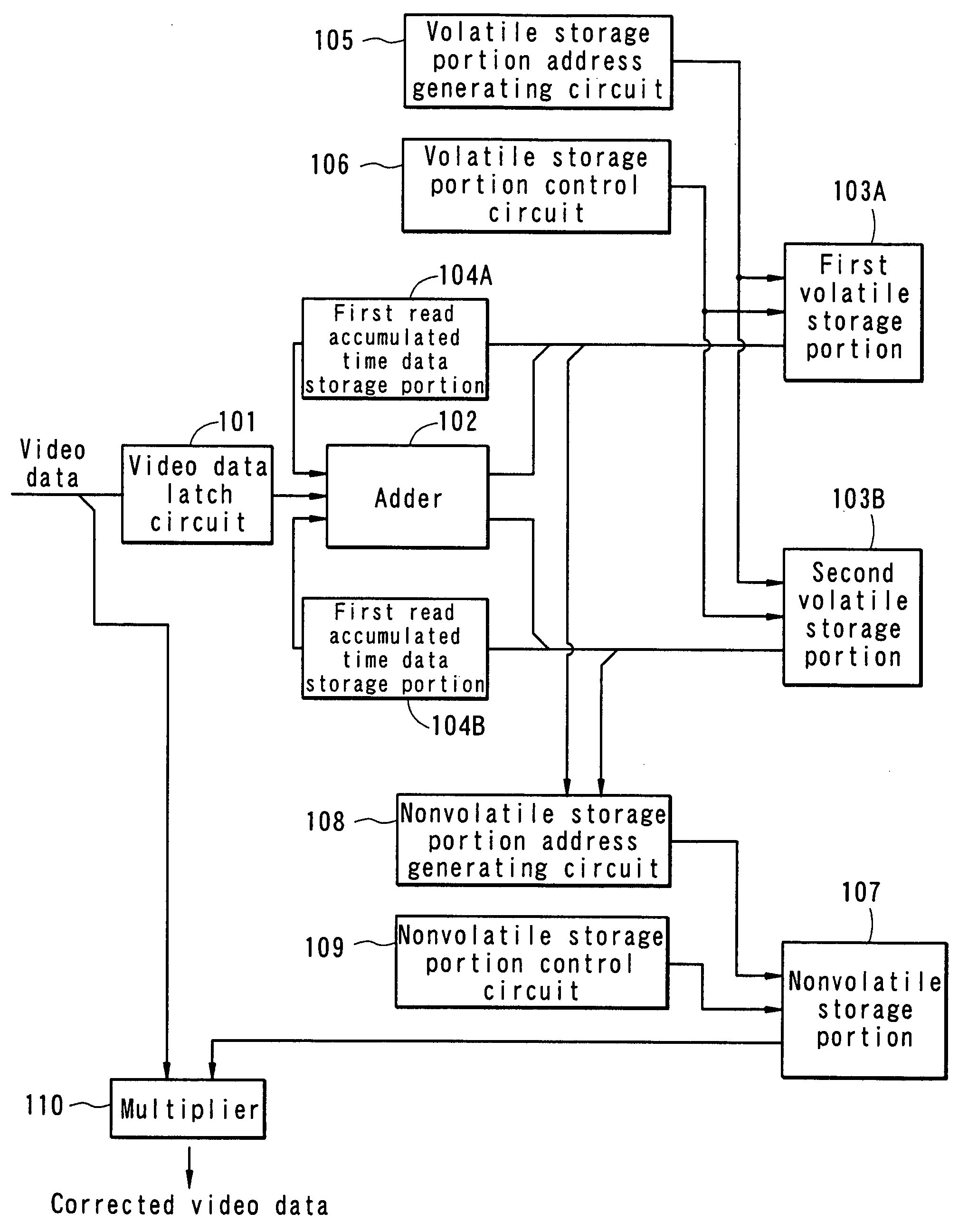
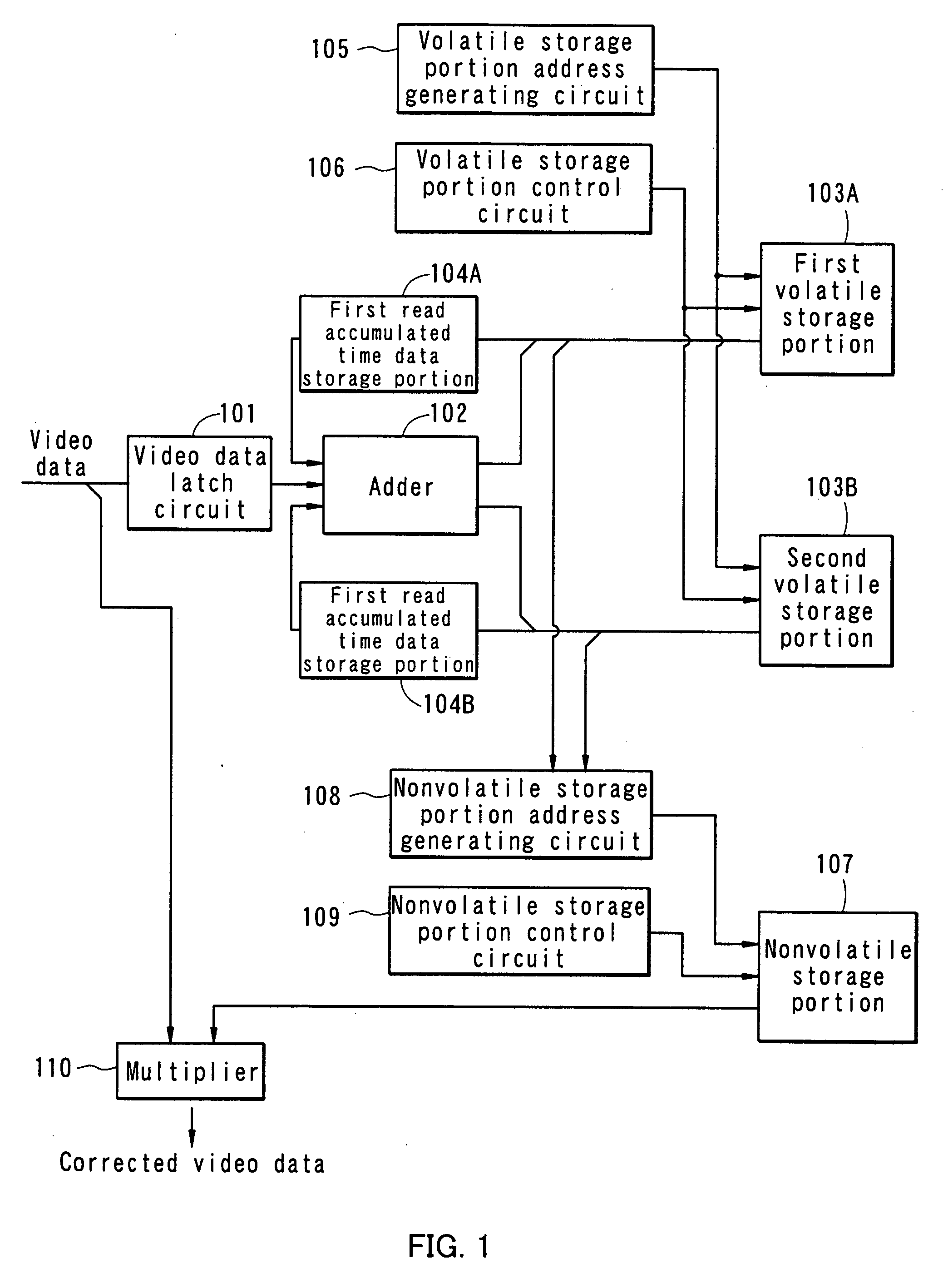
[0067]FIG. 1 is a schematic view showing a configuration example of a video data correction circuit according to the invention. The video data correction circuit includes a video data latch circuit 101 for latching video data to be sampled, an adder 102 for generating new accumulated time data by adding lighting time estimated from the sampled video data to the previous accumulated time data, a first volatile storage portion 103A and a second volatile storage portion 103B each of which is a volatile storing means for storing accumulated time data, a nonvolatile storage portion 107 that is a nonvolatile storing means for storing a degradation coefficient and creating a backup of the content of the first volatile storage portion 103A and the second volatile storage portion 103B when the power is turned off, and a multiplier 110 for generating corrected video data by multiplying the video data by a degradation coefficient corresponding to accumulated lighting time of each pixel.
[0068]...
embodiment mode 2
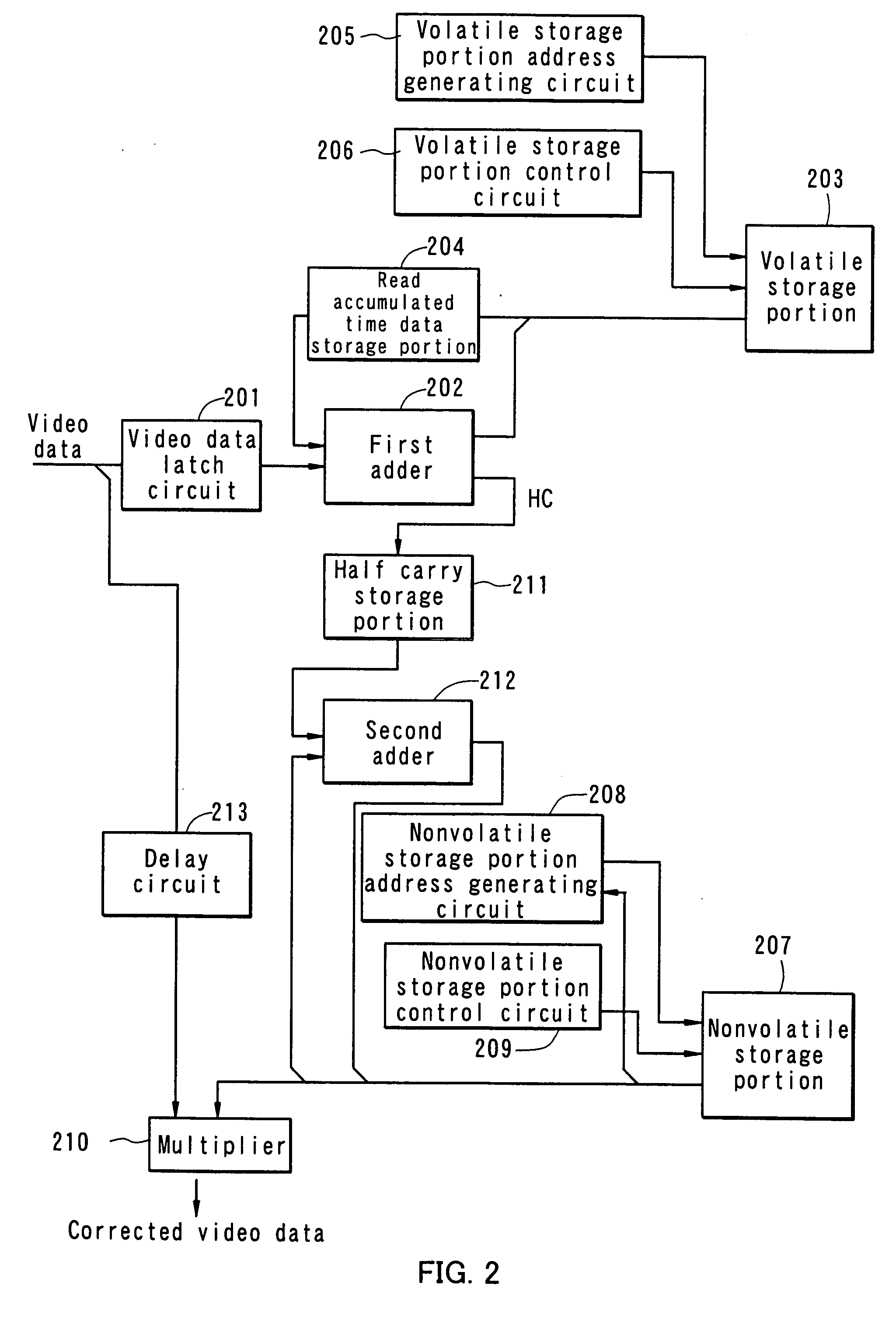
[0079]FIG. 2 is a schematic view showing a configuration example of a video data correction circuit of the invention, which is different than the one shown in Embodiment Mode 1. The video data correction circuit shown in Embodiment Mode 2 has a similar configuration to the one shown in Embodiment Mode 1, except in that only one volatile storage portion is provided to store the lower bit and half carry of accumulated time data and the upper bit of the accumulated time data is stored in the remaining address area of a nonvolatile storage portion.
[0080] The configuration and operation of the video data correction circuit according to this embodiment mode are described more specifically with reference to FIG. 2. The video data correction circuit includes a video data latch circuit 201 for latching video data to be sampled, which functions as a lighting time accumulated portion, a volatile storage portion 203 for storing the lower bit and half carry (one or more bits) of accumulated tim...
embodiment mode 3
[0092] In this embodiment mode, the lower bit of accumulated lighting time data produced by a video data correction circuit is stored in an unused address area of a storing means such as a video memory used in a display control circuit, while the upper bit of the accumulated lighting time data is stored in a nonvolatile storing means, and the data is read as needed to correct video data. That is to say, the video data correction circuit described in Embodiment Modes 1 and 2 is integrated with a control circuit of a display device. Note that the control circuit of a display device converts the format of a received video signal to be able to perform gray scale display in pixels of a display panel, writes the converted video data to a storing means, and outputs to the display panel a panel control signal and the video data read from the storing means for displaying images.
[0093]FIG. 3 is a schematic view of an integrated control circuit where a video data correction circuit of the inv...
PUM
 Abstract
Description
Claims
Application Information
 - R&D
- Intellectual Property
- Life Sciences
- Materials
- Tech Scout
- Unparalleled Data Quality
- Higher Quality Content
- 60% Fewer Hallucinations
Browse by: Latest US Patents, China's latest patents, Technical Efficacy Thesaurus, Application Domain, Technology Topic, Popular Technical Reports.
© 2025 PatSnap. All rights reserved.Legal|Privacy policy|Modern Slavery Act Transparency Statement|Sitemap|About US| Contact US: help@patsnap.com


