Aortic annuloplasty ring

Active Publication Date: 2006-01-19
CORONEO
View PDF30 Cites 242 Cited by
  • Summary
  • Abstract
  • Description
  • Claims
  • Application Information

AI Technical Summary

Benefits of technology

[0013] Advantages of the present invention include that the proposed annuloplasty ring, by virtue of its scalloped shape, allows fixation of said ring in general proximity to the fibrous annulus of the native valve, and as such advantageously offers a dynamic ring design able to deflect a predetermined desired amount to modulate or control key dimension

Problems solved by technology

While some of the surgical corrections are better adapted to the aortic physiology, others, less convenient, have been associated with recurrent aortic disease and valvular insufficiency.
In a diseased aorta, the dilatation of the aortic root or valve annulus, or the aneurysm of the aortic wall, results in compromised leaflet coaptation leading to regurgitation and valve insufficiency.
This ensuing condition, known as aortic insufficiency, can severely diminish the heart's ability to effectively deliver blood to the rest of the body or to the heart muscle, and can lead to serious complications and death.
One of the drawbacks of this surgical intervention, known as the Bentall procedure, is that in patients having relatively healthy leaflets, such leaflets are sacrificed and replaced by a prosthetic valve in order to correct the aortic dilatation.
In addition, there is a need for prolonged anti-coagulation therapy in the case of Bentall procedures using mechanical heart valves, and a risk of valve degradation and reoperation in the case of Bentall procedures using bioprosthetic heart valves.
The procedure is generally long and difficult to perform, and often results in leaflet impact or concussion with the walls of the Dacron prosthesis during the ejection phase of the cardiac cycle.
In addition, the absence of radial compliance of the Dacron root prosthesis does not allow for an increase in diameter at the sinotubular junction STJ during ejection, which is an important aspect in providing optimal

Method used


Image

  • Aortic annuloplasty ring
  • Aortic annuloplasty ring
  • Aortic annuloplasty ring

Examples


first embodiment

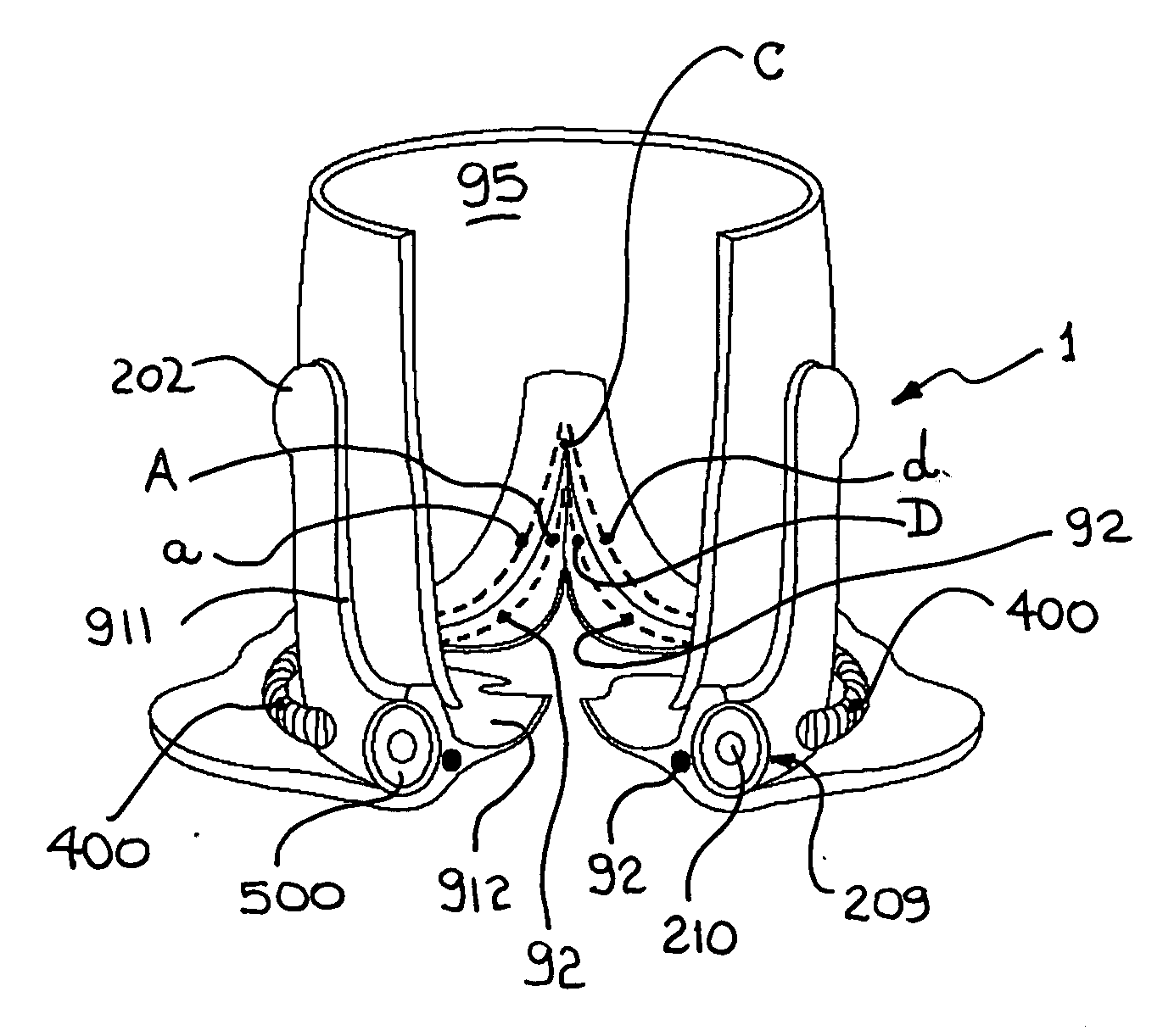
[0059] Referring now to FIGS. 4-6, ring 1 will be described in greater detail. Ring 1 consists of an undulated or scalloped three-peak ring structure, or space frame 200 and an annulus-restraining means or annulus-limiting member 400. Frame 200 is configured to form a closed, non-planar, continuous band including three trough sections 201 located in proximity to ring plane BASE, and three crest sections 202 located in proximity to ring plane TOP. Said crest sections are circumferentially interspersed between said trough sections. Said undulated space frame 200 is preferably constructed from three substantially U-shaped frame members 210. Said three frame members 210 are connected at the three resulting crests sections 202 at top 207 of ring 1 by three crown plates, end connectors, or fittings 300, and coupled at the base 206 of ring 1 by three hoop-closing members, tethers, ties or restraints 401.

[0060] Each of U-shaped frame members 210 is defined by a concave base 211 from which e...

fifth embodiment

[0100] In a variant of this fifth embodiment, illustrated in FIG. 18B, ring 5 is configured with the elastomeric layer or sheath 500 extending below crest sections 202 and end fittings 300, and is draped between two adjacent U-shaped frame members 210 in a manner to substantially cover infra-commissure zone 204 with an elastomeric web 462. Elastomeric web 462 may be of variable thickness along its height, circumferential width, or both, in order to fine-tune the flexibility or elasticity of said web 462 to allow proper modulation or control of dimensions of aortic root 90 by ring 5. Elastomeric web 462 may also be made from a different material than elastomeric sheath 500. Alternatively, web 462 may be made as a composite construction having fibre reinforcement at strategic locations therein to tailor flexibility of said web in certain directions. Alternatively still, at least a portion of said elastomeric web 462 may also be covered by a textile fabric covering similar to textile f...

sixth embodiment

[0129] Referring now more specifically to FIG. 22C, there is shown a variant composite prosthetic ring-conduit 61 to the sixth embodiment illustrated in FIG. 22A. Variant ring-conduit 61 is different to the ring-conduit 6 in that it includes a variant prosthetic conduit 74, said conduit 74 however is still advantageously attached or integral with ring 81 to form a composite ring-conduit assembly 61. Conduit 74 is constructed from a substantially elastic biomaterial such as a hydrogel, or any other like elastic biomaterial suitable for implant use and for contact with blood. More specifically, conduit 74 is preferably constructed from a cryogel polyvinyl alcohol (cPVA) having been cross-linked by repeat freeze-thaw cycles to obtain the desired elasticity, similar to native aortic root tissue. Typically, three to five such freeze-thaw cycles may be employed to construct a cPVA biomaterial with the desired representative material properties. Ring 81 is preferably introduced within a mo...


PUM


Abstract

An annuloplasty ring to resize a dilated aortic root during valve sparing surgery includes a scalloped space frame having three trough sections connected to define three crest sections. The annuloplasty ring is mounted outside the aortic root, and extends in height between a base plane and a spaced apart commissure plane of the aortic root. At least two adjacent trough sections are coupled by an annulus-restraining member or tether that limits the maximum deflection of the base of the annuloplasty ring. In use, the tether is preferably located in proximity to the base plane of the aortic root. The annuloplasty ring is movable between a first, substantially conical configuration occurring during a diastolic phase of the cardiac cycle, and a second, substantially cylindrical configuration occurring during a systolic phase of the cardiac cycle. The attachment of the annuloplasty ring in proximity to the cardiac valve annulus allows the ring to regulate the dimensions of a dynamic aortic root during the different phases of the cardiac cycle.

Description

[0001] This application claims the benefits of U.S. Provisional Patent Application Ser. No. 60 / 588,745 filed on Jul. 19, 2004.FIELD OF THE INVENTION [0002] The present invention relates to the general field of implantable cardiac devices, and is particularly concerned with annuloplasty devices that may be used to correct valvular insufficiency in valve-sparing procedures. BACKGROUND OF THE INVENTION [0003] Aortic root dilation is one of the most common causes of aortic valve incompetence in North America. Prevalence of surgical corrections for this pathology has increased considerably during the last two decades. Mechanisms involved in this pathology have been experimentally and clinically studied resulting in a variety of surgical corrections. While some of the surgical corrections are better adapted to the aortic physiology, others, less convenient, have been associated with recurrent aortic disease and valvular insufficiency. There is room for improvement in providing a surgical ...

Claims


Application Information

Patent Timeline
IPC IPC(8): A61F2/24
CPCA61F2/06A61F2/2442A61F2/2445
Inventor BULMAN-FLEMING, NEILCARTIER, RAYMONDVALENTINI, VALERIOPAOLITTO, ANTHONY
Owner CORONEO
Why Eureka
Try Eureka