
Flat fluorescent lamp improving discharge efficiency

a fluorescent lamp and discharge efficiency technology, applied in the field of flat fluorescent lamps, can solve the problems of reducing the reliability of the lamp, assembly unit cost, and economic disadvantage of direct type ccfl, and achieve the effects of improving optical efficiency, reducing the discharge initiation voltage, and increasing luminan

Inactive Publication Date: 2006-01-26
LS TECH
View PDF14 Cites 13 Cited by
  • Summary
  • Abstract
  • Description
  • Claims
  • Application Information

AI Technical Summary

Benefits of technology

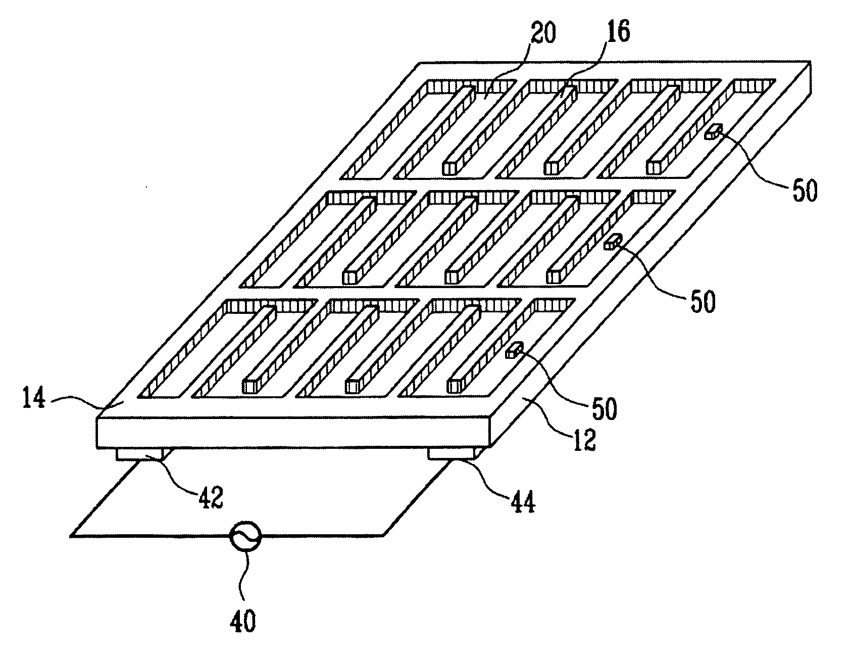
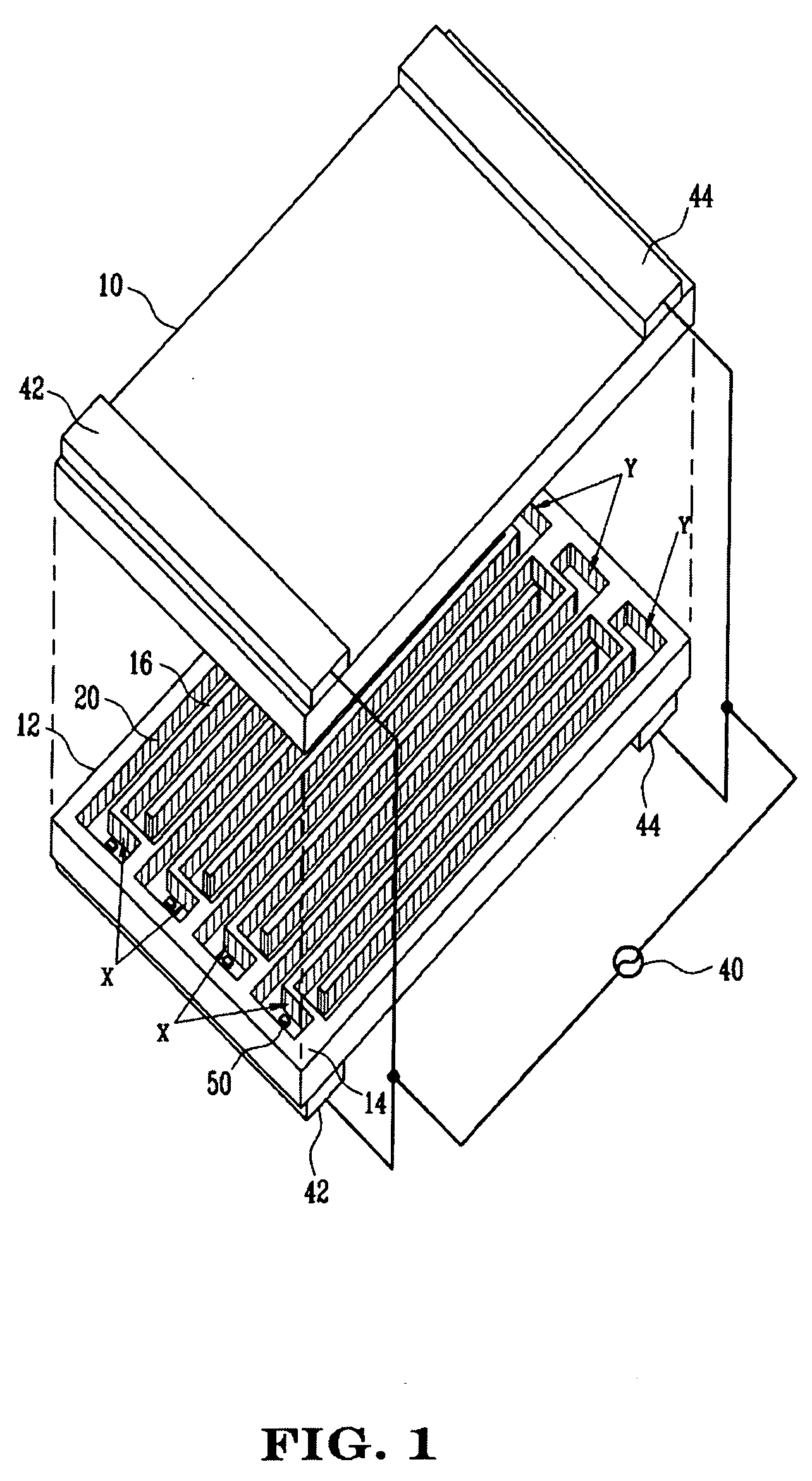
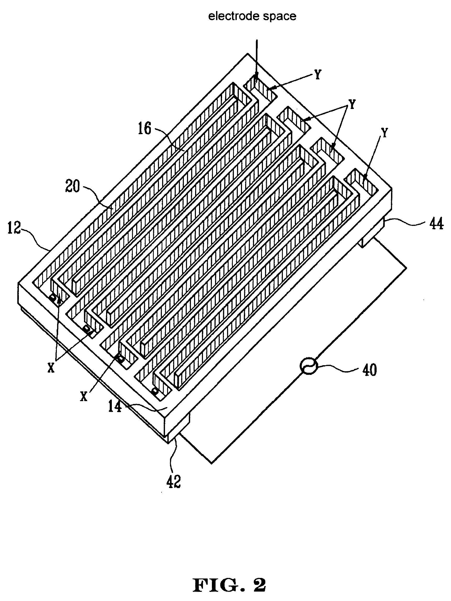
[0021] An object of the present invention is to provide an FFL which can increase luminance and decrease a discharge initiation voltage by improving optical efficiency, by separating one long meandering discharge channel into a plurality of independent meandering discharge channels, disposing electrode spaces in the starting and terminating ends of each discharge channel, and arranging discharge electrodes in the electrode spaces.
[0022] Another object of the present invention is to provide an FFL including discharge electrodes having an external electrode structure to stably discharge a plurality of discharge channels by a small number of inverters, and to provide an FFL including discharge electrodes having an internal and external electrode structure to reduce non-luminescent regions of the external electrodes and improve luminescence efficiency.
[0023] Yet another object of the present invention is to provide an FFL which can lower a discharge initiation voltage and maximize discharge efficiency, by forming main discharge electrodes and auxiliary electrodes, connecting the auxiliary electrodes to the main discharge electrodes and applies the same voltage, temporarily applying power at the initial stage of the discharge operation and floating the auxiliary electrodes during the discharge operation, or disposing the auxiliary electrodes in the form of floating electrodes.
[0024] Yet another object of the present invention is to provide an FFL having special shapes of internal electrodes and internal electrode curved units for easy assembly, lamp reliability and stable operation.

Problems solved by technology

The direct type CCFL uses a few tens of lamps, which reduces lamp reliability of the LCD.
Also, the direct type CCFL is economically disadvantageous due to the high assembly unit cost.
The edge type CCFL irradiating a light from the end cannot obtain sufficient luminance for a large-sized LCD panel.
Accordingly, an output voltage of an inverter rises, and power loss occurs by electronic wave failure and voltage leakage.
When the CCFL type FFL is used as the backlight unit, the LCD is not suitable for home use.
However, each discharge space cannot be efficiently exhausted, and an inverter must be installed in each discharge channel.
As a result, the unit cost of production increases.
An increased dead space of the lamp deteriorates the outer appearance of the lamp.
Therefore, power consumption increases to obtain an appropriate current density in each discharge channel.
The direct current discharge type electrodes in which the direct current flows due to metal electrodes exposed to discharge spaces cannot stably control the discharge operation in low luminance, and the alternating current discharge type electrodes having their both ends coated with a dielectric layer cannot attain high luminance due to a low current.
As a result, there are difficulties in manufacturing the large-sized lamp and improving optical efficiency thereof.

Method used


Image

  • Flat fluorescent lamp improving discharge efficiency
  • Flat fluorescent lamp improving discharge efficiency
  • Flat fluorescent lamp improving discharge efficiency

Examples


Embodiment Construction

[0044] A flat fluorescent lamp (FFL) improving discharge efficiency in accordance with the present invention will now be described in detail with reference to the accompanying drawings. In the following description, same drawing reference numerals are used for the same elements even in different drawings.

[0045] Referring to FIG. 1, in the FFL, two facing substrates, namely, a front substrate 10 and a rear substrate 12 are bonded with a sidewall 14 therebetween. FIG. 2 shows the detailed structure of the rear substrate 12.

[0046] The sidewall 14 externally isolates discharge spaces formed between the two substrates 10 and 12. As shown in FIGS. 1 and 2, the sidewall 14 can be incorporated with the rear surface 12, or bonded to the rear substrate 12 by a sealing member (for example, low melting point glass such as frit glass) according to the intention of the manufacturer.

[0047] In addition, the sidewall 14 can be separately formed from cross walls 16 discussed later or incorporated ...


PUM


Abstract

The present invention discloses a flat fluorescent lamp which can improve discharge efficiency and luminance by increasing a current density per discharge channel by forming a plurality of independent meandering discharge channels on a rear substrate, lowering a discharge initiation voltage by auxiliary electrodes and internal and external discharge electrodes, and minimizing non-luminescent regions by the external electrodes. A sidewall is installed to form an airtight space between front and rear substrates, cross walls for forming a plurality of independent meandering discharge channels are installed on the rear substrate, and discharge electrodes are disposed at both sides of the starting and terminating ends of the plurality of meandering discharge channels, for discharging the meandering discharge channels in parallel.

Description

CLAIMING FOREIGN PRIORITY [0001] The applicant claims and requests a foreign priority, through the Paris Convention for the Protection of Industrial Property, based on a patent application filed in the Republic of Korea (South Korea) with the filing date of Jul. 26, 2004, with the patent application number 10-2004-0058290, by the applicant, the contents of which are incorporated by reference into this disclosure as if fully set forth herein. TECHNICAL FIELD [0002] The present invention relates to a flat fluorescent lamp, and more particularly to, a flat fluorescent lamp which can improve discharge efficiency and luminance by increasing a current density per independent discharge channel by forming a plurality of independent meandering discharge channels, lowering a discharge initiation voltage by improving an electrode structure, and removing non-luminescent regions by external electrodes by forming electrode spaces having a larger width than the discharge channels. BACKGROUND ART [...

Claims


Application Information

Patent Timeline
Patent Type & Authority Applications(United States)
IPC IPC(8): G09G3/10
CPCH01J61/0672H01J65/046H01J61/547H01J61/307
Inventor PARK, DEUK-ILRHEW, CHOONG-YOP
Owner LS TECH
Learn More