[0056] The color inks and invisible ink are supplied to each recording head passing through a tube for
piping from a
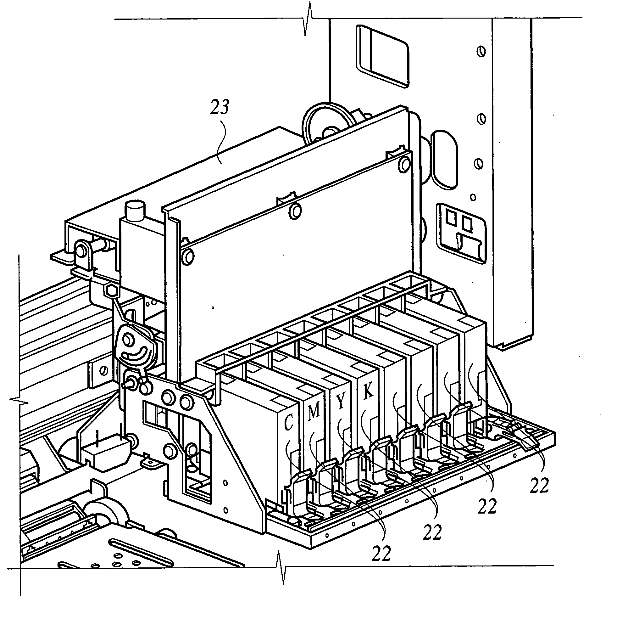
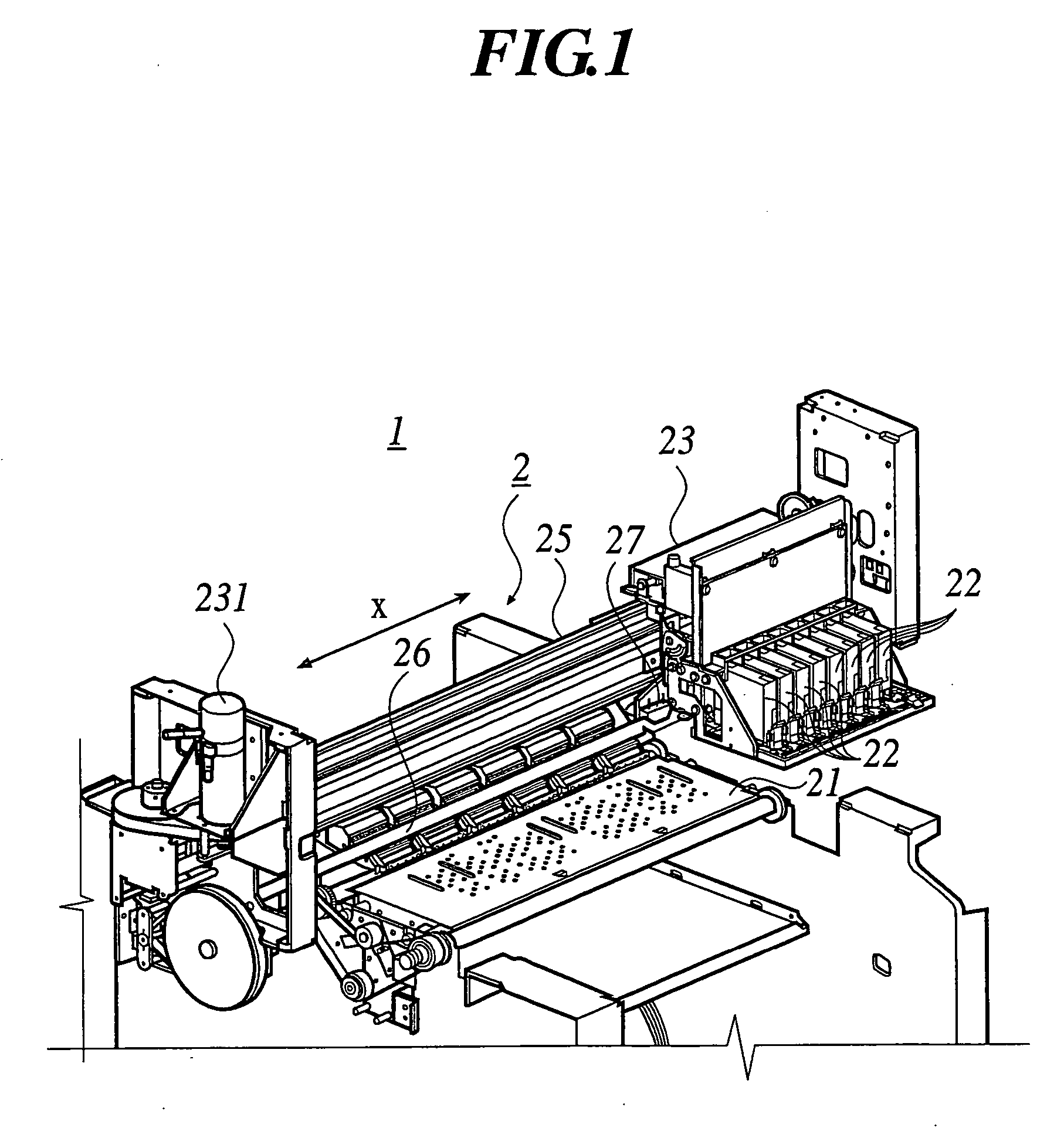
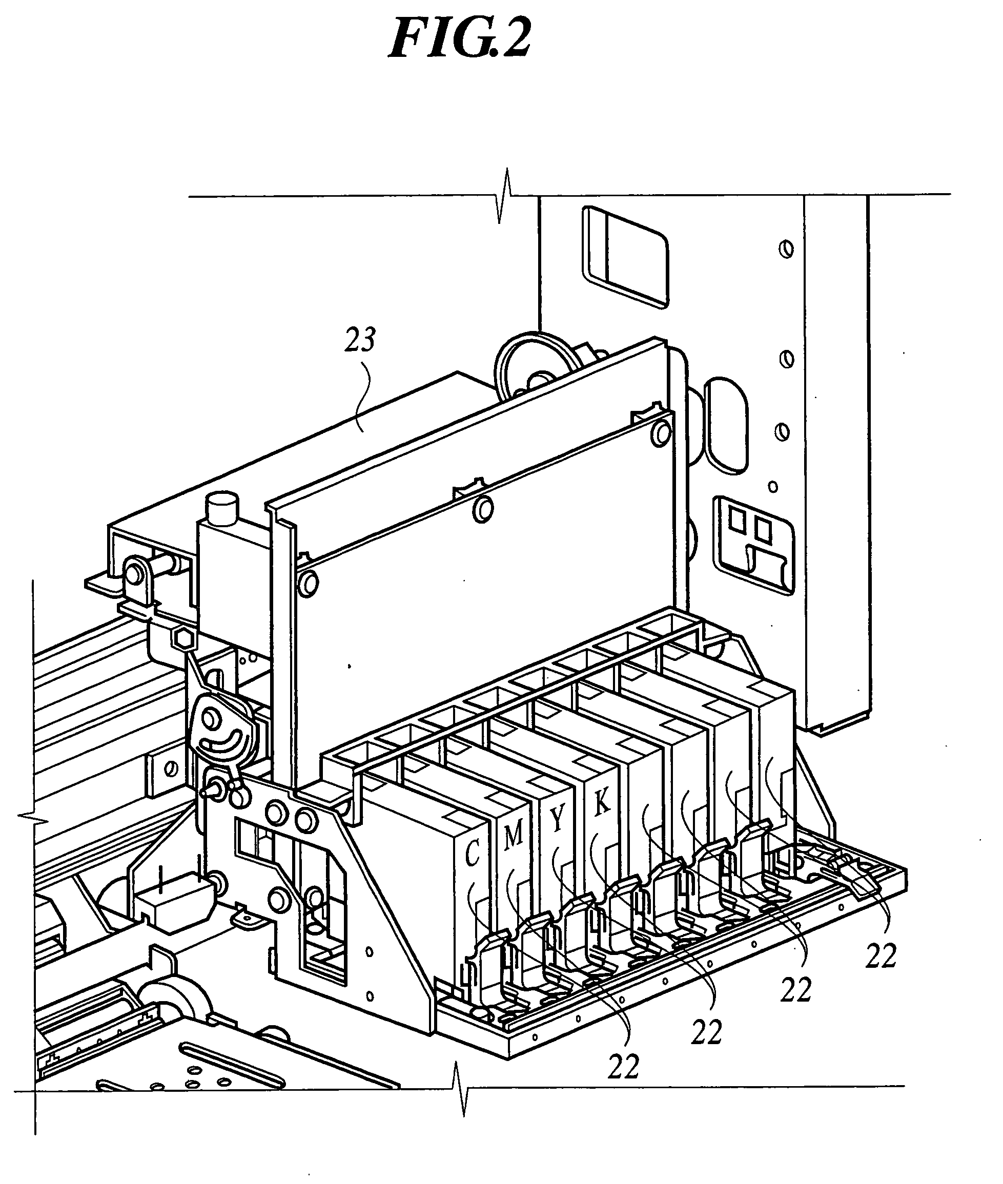
cartridge for recording ink which is not shown in the figure. As shown in FIGS. 1 and 2, eight pieces of recording heads 22 are disposed side by side along the scanning direction, and the recording head is composed of the first recording head for color inks, which are used for inks such as light color inks and special color ink as well as 4 color inks of cyan (C),
magenta (M), yellow (Y) and black (K) and 3 special color inks, and respectively, and the second recording head for the invisible ink. The above embodiment shows the case where four inks of C, M, Y and K and special color ink are used. However, the same effect of the invention can be obtained in the inkjet printer where
pale color ink is used in combination with C, M, Y and K for recording.
[0057] Next, An image forming method of the thinned-out image is illustrated, where the first recoding head jetting color inks scans a plural times at a same recording area of a recording medium to form the thinned-out image according to a
thinning-out pattern irregular between each of the scanning steps.
[0058] First, a control section of the inkjet printer 1 is illustrated in reference to FIG. 4. FIG. 4 is a
block diagram representing the control section of the inkjet printer 1.
[0059] As shown in FIG. 4, the control section 100 is configured by connecting a feeding motor 101 to feed the recording medium, CPU 103, an interface 104, a driving motor 231 for the
carriage, a memory write controller 105, an image memory 106, a memory read controller 107, and a
mask processing circuit 108 through a
bus 110 as is shown. A detailed configuration of the
mask processing circuit 108 is described below. The recording heads 22 of the inkjet printer 1, respective driving sections and the like are also connected to the control section 100.
[0060] The control section 100 controls feeding of the recording medium, scanning operation of the
carriage 23 and color inks jetting of the recording heads 22, and the like. As is shown in FIG. 4 and FIG. 5, an image forming apparatus 200 such as computer is connected. The image forming apparatus 200 forms an image with multiple colors based on input signals. In this instance, an application program 201 which operates inside the image forming apparatus 200 displays the image on a monitor 300 through a video driver 202 with
processing the image. When this application program 201 puts an
image formation direction in motion, the printer driver 203 of the image forming apparatus 200 receives image data for the
image formation from the application program 201, and the image data are converted into signals capable of forming the image in the inkjet printer 1.
[0061] The printer driver 203 comprises a rasterizer 204 which converts the image data dealt in the application program 201 into image
gradation data including color information of dot units, a color
gradation compensation module 205 which compensates the image
gradation data in accordance with color density property and gradation property of the inkjet printer 1, and a
halftone module 206 which produces the image data of so-called
halftone where a density at a certain area is expressed by the presence or absence of the recording inks at dot units from the image data after the
color compensation. A module 207 which performs the thinning-out mask processing can be also incorporated in this printer driver. In that case, a mask setting can be changed depending on a medium type used for the printing, and thus more flexible control is possible than the processing in the printer. When the mask processing circuit 108 is used, the processing at the module 207 is not performed. Conversely, when the mask processing is performed at the module 207, the processing at the mask processing circuit 108 is not performed. Also, it is possible to download a mask pattern every printing from the
image processing apparatus 200.

