Miniaturised relay and corresponding uses thereof

a relay and miniaturisation technology, applied in the direction of micromechanical switches, gyroscopes/turn-sensitive devices, acceleration measurement using interia forces, etc., can solve the problems of reducing the useful life and reliability of the relay, and reducing the frictional force. , to achieve the effect of reducing frictional force, avoiding sticking and high frictional forces

Inactive Publication Date: 2006-02-02
BAOLAB MICROSYST
View PDF11 Cites 4 Cited by
  • Summary
  • Abstract
  • Description
  • Claims
  • Application Information

AI Technical Summary

Benefits of technology

[0046] To avoid sticking and high frictional forces it is advantageous that the conductive element have rounded external surfaces, preferably that it be cylindrical or spherical. The spherical solution minimises the frictional forces and sticking in all directions, whilst the cylindrical solution, with the bases of the cylinder facing the first and second zone allow reduced frictional forces to be achieved with respect to the lateral walls whilst having large surfaces facing the condenser plates—efficient as concerns generation of electrostatic forces. This second solution also has larger contact surfaces with the c

Problems solved by technology

However miniaturisation techniques require the use of activation voltages and surfaces which are as small as possible.
Relays known in the state of the art have several problems impeding their advance in this respect.
A manner of reducing the activation voltage is precisely to increase the relay surface areas, which renders miniaturisation difficult, apart from being conducive to the appearance of deformations reducing the useful life and reliability of the relay.
However this implies problems of sticking, since capillary forces are very high, which thus also reduces the useful working life and reliability of these relays.
The use of high activation voltages also has negative effects such as ionisation of the components, accelerated wearing due to strong mechanical solicitation and the electric noise which the relay generates.
Electrostatic relays also have a significant problem as to reliability, due to the phenome

Method used


Image

  • Miniaturised relay and corresponding uses thereof
  • Miniaturised relay and corresponding uses thereof
  • Miniaturised relay and corresponding uses thereof

Examples


Embodiment Construction

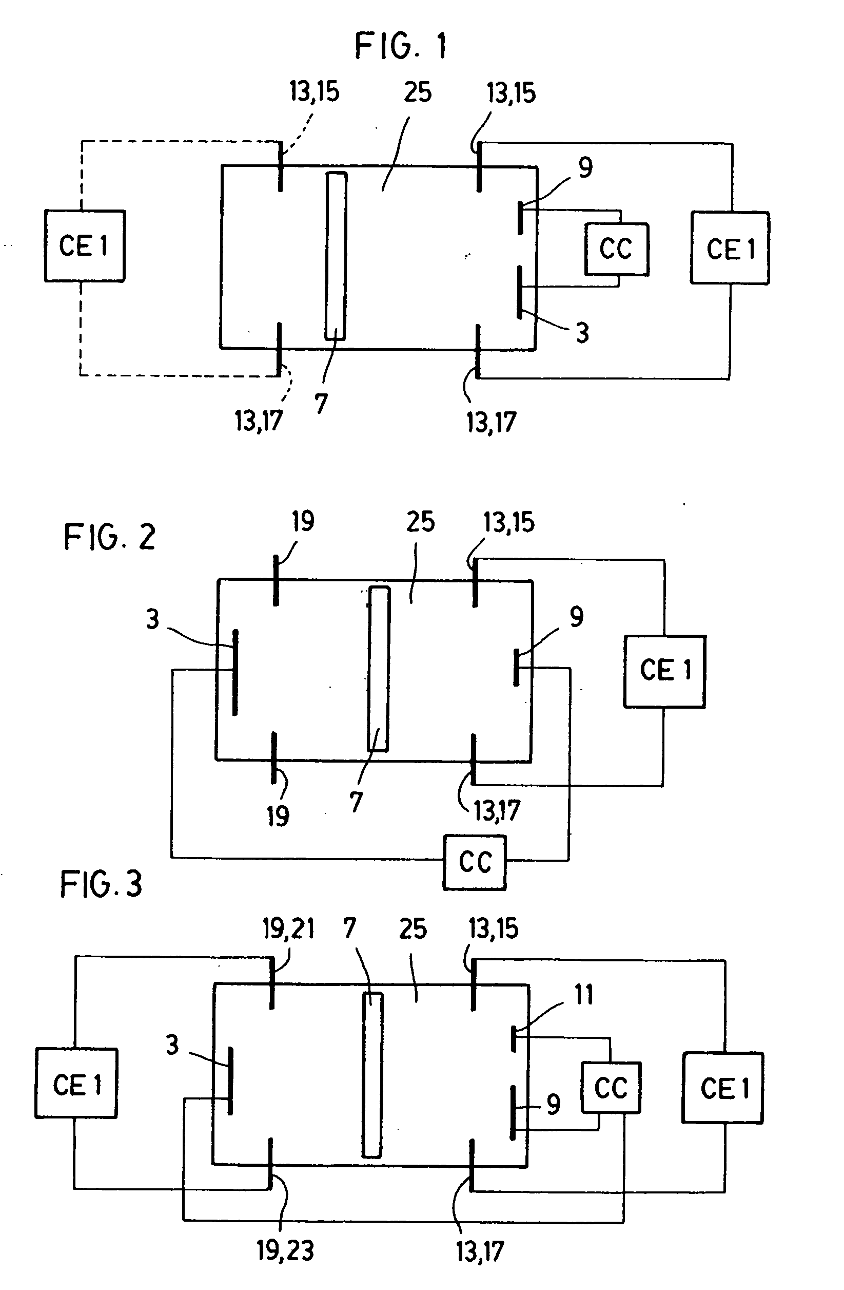
[0082]FIG. 1 shows a first basic functioning mode of a relay according to the invention. The relay defines an intermediate space 25 in which is housed a conductive element 7, which can move freely along the intermediate space 25, since physically it is a detached part which is not physically joined to the walls which define the intermediate space 25. The relay also defines a first zone, on the left in FIG. 1, and a second zone, on the right in FIG. 1. In the second zone are arranged a first condenser plate 3 and a second condenser plate 9. In the example shown in FIG. 1 both condenser plates 3 and 9 have different surface areas, although they can be equal with respect to one another. The first condenser plate 3 and the second condenser plate 9 are connected to a CC control circuit. Applying a voltage between the first condenser plate 3 and the second condenser plate 9, the conductive element is always attracted towards the right in FIG. 1, towards the condenser plates 3 and 9. The c...


PUM


Abstract

A miniaturized relay having a first zone facing a second zone, a first condenser plate, a second condenser plate arranged in the second zone, and smaller than or equal to the first plate, an intermediate space between both zones, a conductive element arranged in the intermediate space and which is mechanically independent from the adjacent walls and can move freely across the intermediate space depending on voltages present between both plates, contact points of an electric circuit, in which the conductive element closes the electric circuit by making contact with the contact points. Such relays can be used, for example, as: accelerometers, accelerometers in airbags, tiltmeters, Coriolis force detectors, microphones, in acoustic applications, pressure sensors, flow sensors, temperature sensors, gas sensors and magnetic field sensors.

Description

FIELD OF THE INVENTION [0001] This invention relates to a miniaturised relay. The invention also refers to different uses for miniaturised relays according to the invention. STATE OF THE ART [0002] Currently there are various alternatives for the production of miniaturised relays, in particular, in the context of technologies known as MEMS technology (micro electromechanical systems), Microsystems and / or Micromachines. In principal such may be classified according to the type of force or actuation mechanism they use to move the contact electrode. The classification usually applied is thus between electrostatic, magnetic, thermal and piezoelectric relays. Each one has its advantages and its drawbacks. However miniaturisation techniques require the use of activation voltages and surfaces which are as small as possible. Relays known in the state of the art have several problems impeding their advance in this respect. [0003] A manner of reducing the activation voltage is precisely to in...

Claims


Application Information

Patent Timeline
IPC IPC(8): H01H57/00G01C19/56G01P15/093G01P15/13H01H35/02H01H35/14H01H35/24H01H36/00H01H59/00H01Q3/12H01Q21/06
CPCG01C19/5726G01C19/5755G01P15/093G01P15/131H01H35/02H01H2037/008H01H35/24H01H36/00H01H59/0009H01H2036/0093H01H35/14G02F1/29G02F1/21
Inventor MONTANYA SILVESTRE, JOSEP
Owner BAOLAB MICROSYST
Why Eureka
Try Eureka