Displaying optical system and image projection apparatus
a technology of optical system and image, applied in the field of display optical system, can solve the problems of difficult downsizing of optical system, degradation of image quality in displayed image, etc., and achieve the effect of reducing speckle noise and light loss
- Summary
- Abstract
- Description
- Claims
- Application Information
AI Technical Summary
Benefits of technology
Problems solved by technology
Method used
Image
Examples
embodiment 1
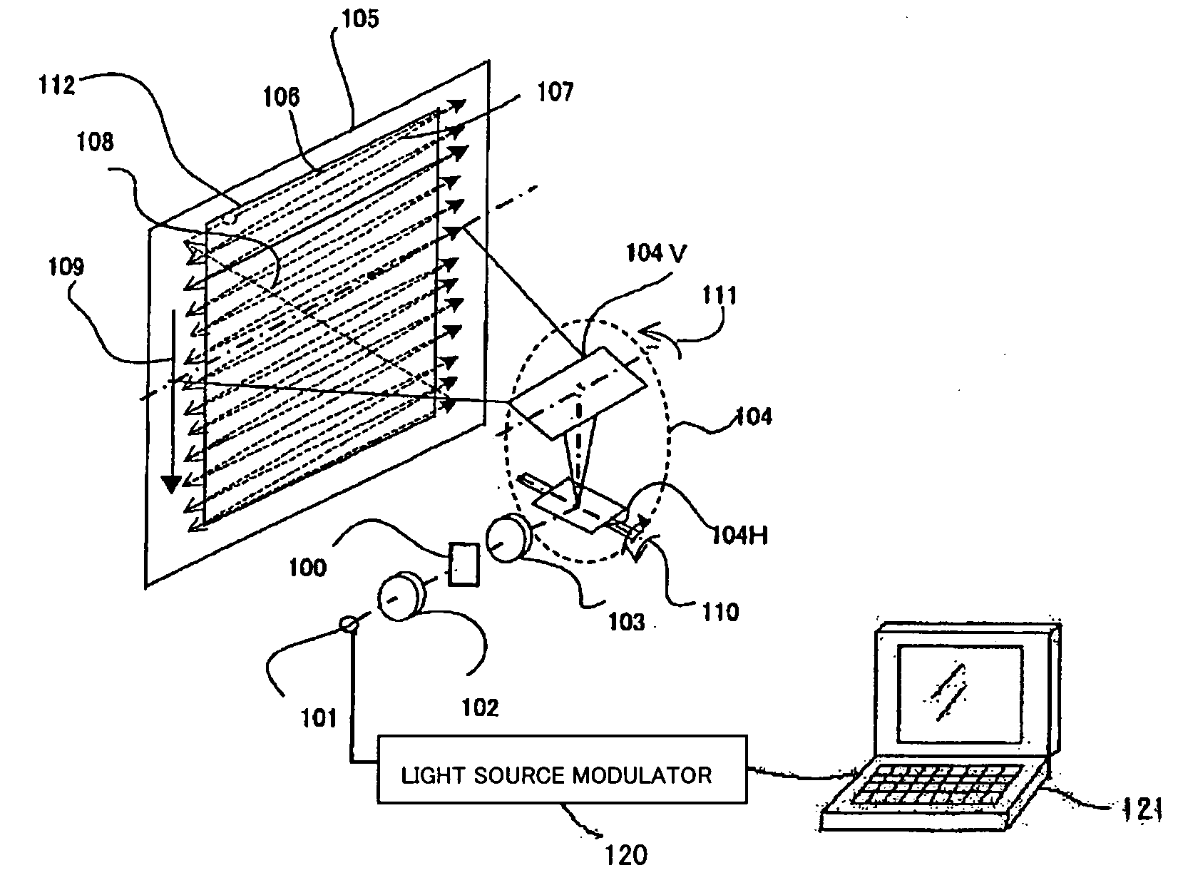
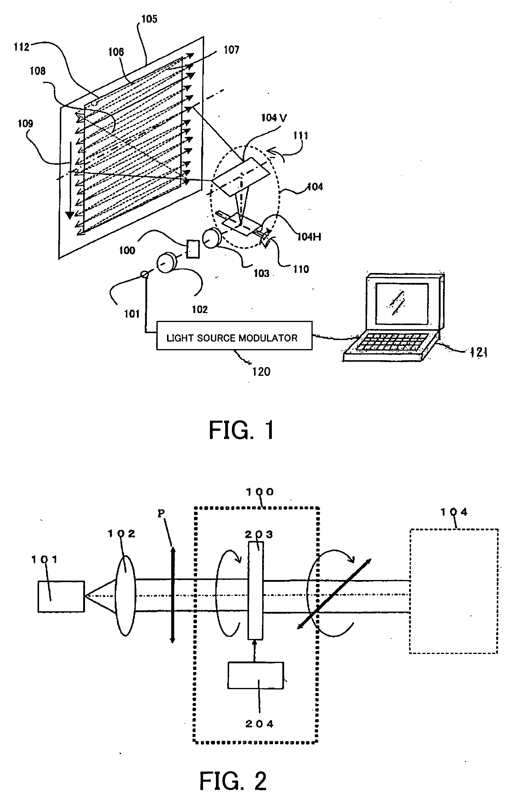
[0022]FIG. 1 shows a displaying optical system for an image projection apparatus that is Embodiment 1 of the present invention. In FIG. 1, reference numeral 101 denotes a laser source which is a light source emitting coherent light. The luminous flux emitted from the laser source 101 is converted into a substantially parallel luminous flux by a collimator lens 102.
[0023] A light-source modulator 120 is connected to the laser source 101. The light-source modulator 120 modulates the intensity of the laser light emitted from the laser source 101 according to image signals input from an image-signal supplying apparatus 120 such as a personal computer, DVD player, video cassette recorder, or television tuner.
[0024] The substantially parallel luminous flux (hereinafter, it is referred to as a laser beam) emerged from the collimator lens 102 enters a polarization control unit 100 which changes the polarization state of the laser beam temporally. A detailed description of the polarization...
embodiment 2
[0066]FIG. 8 shows a horizontal section of a displaying optical system used in an image projection apparatus that is Embodiment 2 of the present invention. This embodiment uses three color laser sources of red, green and blue.
[0067] The divergent luminous fluxes emitted from the red laser source 501-a, green laser source 501-b, and blue laser source 501-c are converted into substantially parallel luminous fluxes by collimator lenses 502-a, 502-b and 502-c, respectively, and then combined by a cross-dichroic prism 510. The luminous flux (laser beam) emerged from the cross-dichroic prism 510 enters a polarization control unit 500.
[0068] The laser beam emerged from the polarization control unit 500 enters an illumination optical system 503. The illumination optical system 503 enlarges the diameter of the entering laser beam, and converts the laser beam into a substantially parallel luminous flux to irradiate a spatial light modulator 504 with the laser beam.
[0069] The spatial light ...
embodiment 3
[0073]FIG. 9 is a schematic block diagram showing a displaying optical system used for an image projection apparatus that is Embodiment 3 of the present invention. The displaying optical system in this embodiment has basically the same configuration as that of the displaying optical system in Embodiment 1. However, in this embodiment, a polarization control unit 600 has a wobbling function which changes the impinging position of the laser beam on the scan surface temporally within a range of approximate one pixel.
[0074] As Embodiment 1, the divergent luminous fluxes emitted from the laser source 101 are converted into a substantially parallel luminous flux by the collimator lens 102, and then enters the polarization control unit 600. The laser beam emerged from the polarization control unit 600 impinges on the scanning device 104 via the condensing optical system 103, and is scanned on the scan surface. The condensing optical system 103 may be disposed between the scanning device 1...
PUM
 Abstract
Description
Claims
Application Information
 - R&D
- Intellectual Property
- Life Sciences
- Materials
- Tech Scout
- Unparalleled Data Quality
- Higher Quality Content
- 60% Fewer Hallucinations
Browse by: Latest US Patents, China's latest patents, Technical Efficacy Thesaurus, Application Domain, Technology Topic, Popular Technical Reports.
© 2025 PatSnap. All rights reserved.Legal|Privacy policy|Modern Slavery Act Transparency Statement|Sitemap|About US| Contact US: help@patsnap.com


