Biological sample observation system and biological sample observation method

a biological sample and observation system technology, applied in the field of biological sample observation system and biological sample observation method, can solve the problems of difficult observation of difficult to observe the same cell group at each time, and difficult to accurately perform evaluation, so as to reduce the damage to living cells

Inactive Publication Date: 2006-02-02
OLYMPUS CORP
View PDF5 Cites 28 Cited by
  • Summary
  • Abstract
  • Description
  • Claims
  • Application Information

AI Technical Summary

Benefits of technology

[0029] The present invention was achieved in order to solve the above problems, with an object of providing a biological sample observation system wherein the fluorescence intensi

Problems solved by technology

That is to say, if the cell activity is unstable, accurate evaluation becomes difficult to perform.
Therefore, the position for observing the cells differs when the cells are taken-out and put back in, and it has been difficult to observe the same cell group at each time.
In the observation using the transparent constant temperature incubator for microscopy, since the positions of the cells are displaced if the culture solution in the container is exchanged, it has been difficult to observe the same cell group at each time.
However it has been difficult to trace the same cell if the cell culture is performed for a longer period.
In this method, cells in one or several dishes are used for a single observation, and there has been concern of damage to the activity of the cells due to a variety of operations for observation.
As described above, in the method where cells in different dishes are evaluated in each measurement, since the respective dishes do not always have completely the same conditions, i

Method used


Image

  • Biological sample observation system and biological sample observation method
  • Biological sample observation system and biological sample observation method
  • Biological sample observation system and biological sample observation method

Examples


first embodiment

[First Embodiment]

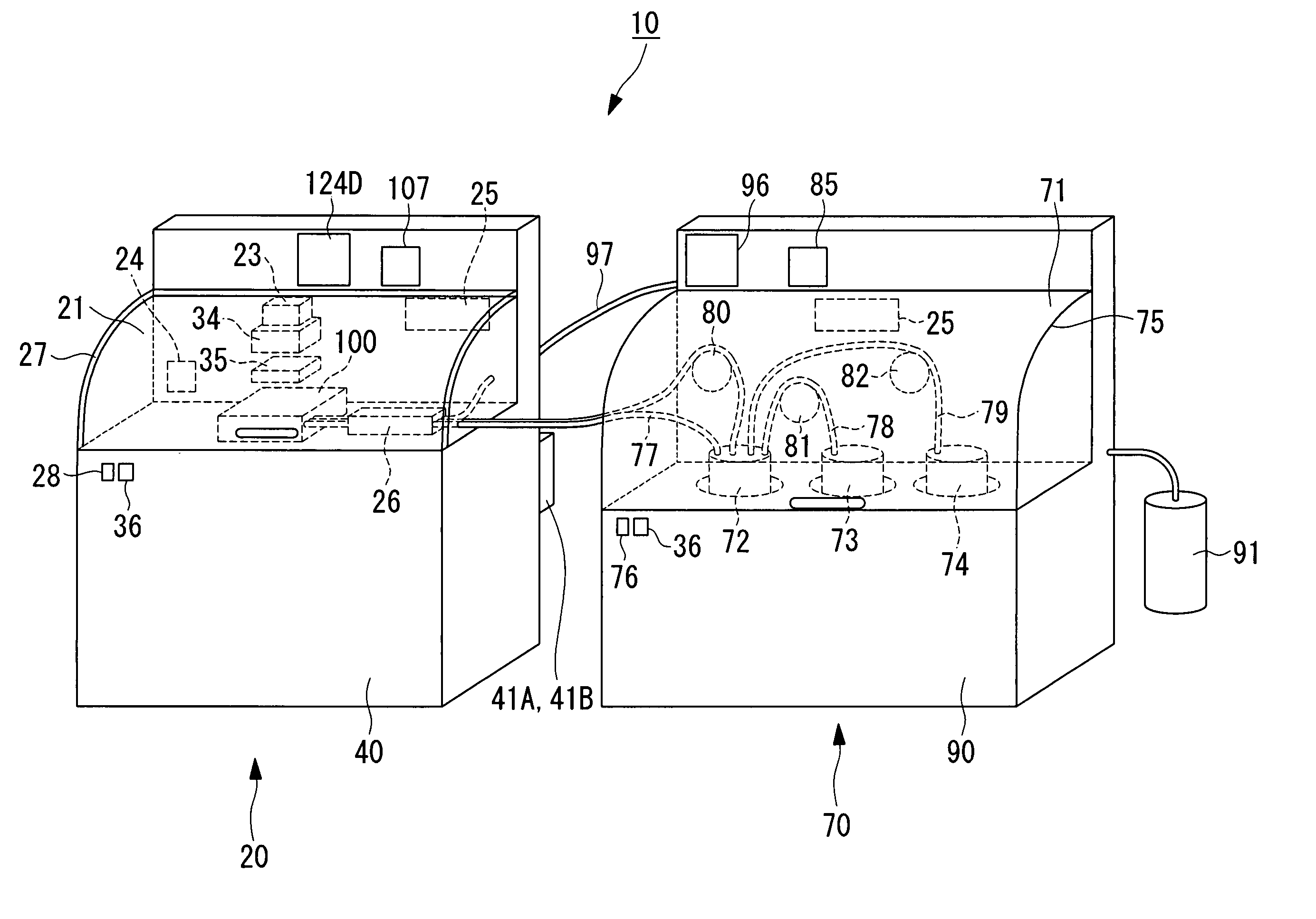
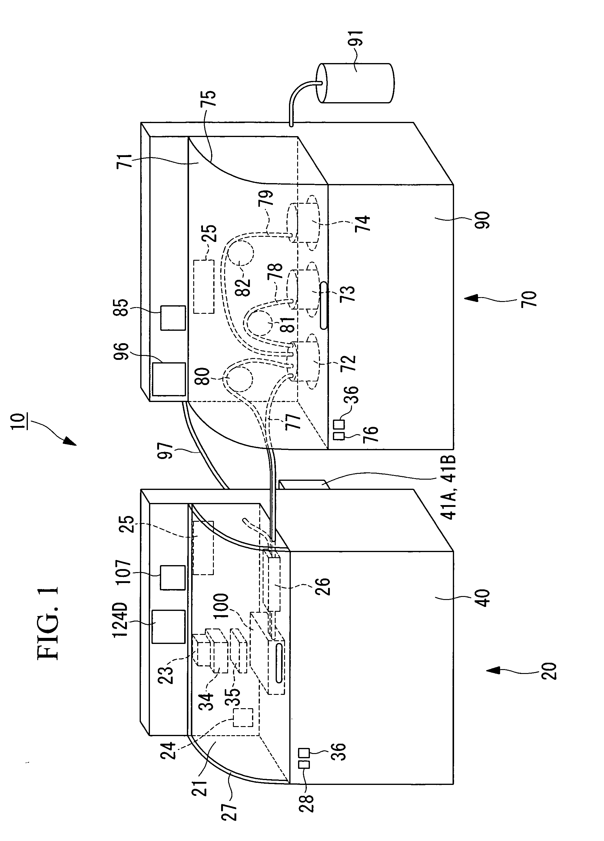
[0058] Hereunder is a description of a biological sample observation system according to a first embodiment of the present invention, with reference to FIG. 1 to FIG. 14B.

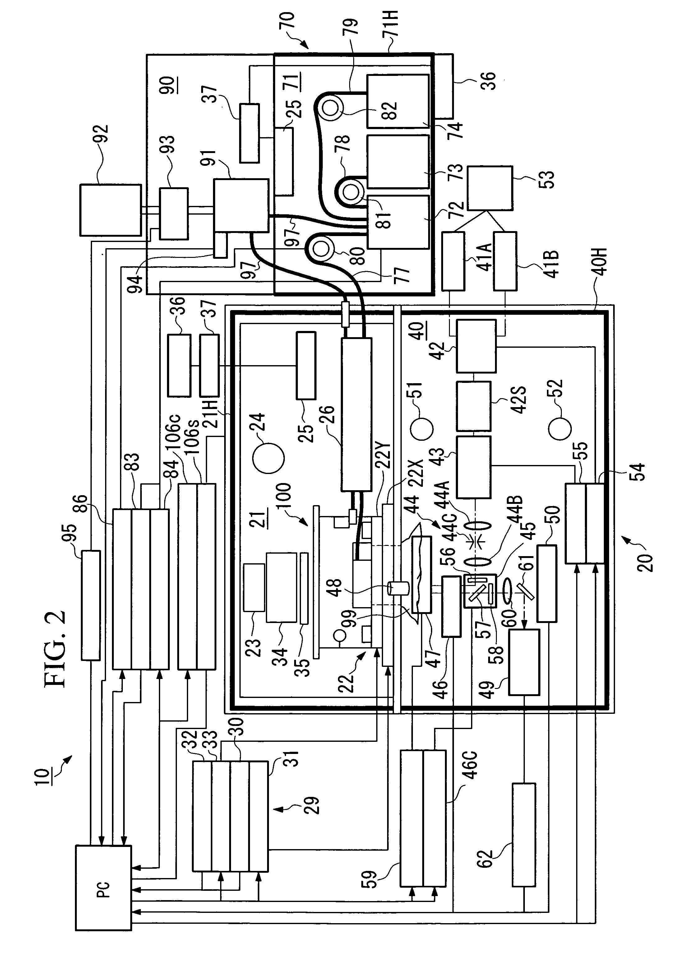
[0059]FIG. 1 is a perspective view showing the outline of the biological sample observation system according to the present embodiment. FIG. 2 is a schematic diagram showing the system structure of the biological sample observation system thereof.

[0060] As shown in FIG. 1 and FIG. 2, a biological sample observation system 10 schematically comprises a detection unit 20, and a culturing unit 70. The detection unit 20 and the culturing unit 70 are desirably arranged close to each other. More preferably, these units 20 and 70 are arranged in contact with each other.

[0061] As shown in FIG. 1 and FIG. 2, the detection unit 20 schematically comprises a heat-insulating box (first zone) 21 for containing a biological sample inside, and a detection section (observation device, second zone) 40 which measu...

second embodiment

[Second Embodiment]

[0263] Next is a description of a second embodiment of the present invention, with reference to FIG. 15A to FIG. 17.

[0264] The basic structure of the biological sample observation system of the present embodiment is similar to that of the first embodiment. However, the structure of the detection unit and the culturing unit is different. Therefore, in the present embodiment, only the vicinity of the detection unit and the culturing unit is described using FIG. 15A to FIG. 17, and the description of the chamber and the like is omitted.

[0265]FIG. 15A is a front view of the biological sample observation system in the present embodiment, and FIG. 15B is a side view of the biological sample observation system in the present embodiment.

[0266] As shown in FIG. 15A and FIG. 15B, the biological sample observation system 200 schematically comprises an inverted type microscope (microscope) 210 and a culturing stage 220. The inverted type microscope 210 and the culturing st...


PUM


Abstract

A biological sample observation system wherein the fluorescence intensity of living cells and the like can be measured accurately in real time, and damage to the living cells can be reduced, and a biological sample observation method using the system are provided. A biological sample observation system for observing change with time in a biological sample being cultured, comprises: a culturing space where an inside environment is maintained at a predetermined level, and the biological sample is cultured under the environment; a buffering space which is formed outside of the culturing space to relieve the effect on the culturing space from the outside of the space, and which is substantially separated from the outside; and a detector which observes the biological sample inside the culturing space through at least a part of the buffering space.

Description

BACKGROUND OF THE INVENTION [0001] 1. Field of the Invention [0002] The present invention relates to a biological sample observation system wherein a biological sample is cultured while it is observed with the passage of time, and to a biological sample observation method which uses the system. [0003] This application is based on Japanese Patent Application No. 2004-180150, the content of which is incorporated herein by reference. [0004] 2. Description of Related Art [0005] With the progress of recent genetic analysis technology, the gene sequences of many living things including humans have been revealed, and the causal relationship between diseases and the analyzed gene products such as proteins is starting to be elucidated little by little. Moreover, in order to comprehensively and statistically analyze various proteins and genes furthermore in the future, consideration is starting to be given to various testing methods and devices using biological samples, in particular cells. [...

Claims


Application Information

Patent Timeline
IPC IPC(8): G02B21/00
CPCC12M41/14G01N21/6486G01N21/6452C12M41/46
Inventor MURAKI, KAYURI
Owner OLYMPUS CORP
Why Eureka
Try Eureka