ESD device for high speed data communication system with improved bandwidth

a data communication system and high-speed technology, applied in the direction of emergency protective arrangement details, overvoltage arrestors using spark gaps, electrical equipment, etc., can solve the problems of discharge of charge on the human body, low yield and field failure, and inability to design chips without esd protection, etc., to achieve minimal disruption of differential signals, reduce the effect of esd events, and reduce the cos

Inactive Publication Date: 2006-02-02
IOWA STATE UNIV RES FOUND
View PDF5 Cites 2 Cited by
  • Summary
  • Abstract
  • Description
  • Claims
  • Application Information

AI Technical Summary

Benefits of technology

[0012] What is needed for chips is an ESD device that allows for high speed data communication while providing adequate ESD protection. Therefore, it is a primary, object, feature, or advantage of the present invention to improve upon the state of the art by providing an ESD device for high speed data communication systems with improved bandwidth.
[0013] It is a further object, feature, or advantage of the present invention to provide a chip that is capable of sending and receiving data at a rate of several Gbits / s without being impeded by parasitic capacitances.
[0014] Another object, feature, or advantage of the present invention is to provide an ESD structure capable of protecting internal circuitry of a chip from high ESD transients.
[0015] A still further, object, feature, or advantage of the present invention is to provide a chip with internal circuitry isolated from the outside world.
[0016] Another object, feature, or advantage of the present invention is to provide a low capacitance ESD structure which is minimally disruptive of differential signals.
[0017] A further object, feature, or advantage of the present invention is to provide an ESD structure for a chip that is reliable and can withstand repeated ESD events effectively.

Problems solved by technology

One of the challenges is the Electrostatic Discharge (ESD) protection devices that are placed at the driver and receiver to protect the chip from ESD events that can be devastating to the chip interior circuitry.
It is very impractical to design a chip with no ESD protection because it becomes very vulnerable to ESD events resulting in lower yield and field failures.
If the human hand touches a chip already charged at a ground potential, a potential difference will result in discharge of the charge on the human body to the chip.
This ESD event can be damaging to the chip.
However, using a large device comes at the cost of increasing parasitic capacitances at the node where the ESD protection is introduced.
If the internal circuitry of the chip does not have ESD protection devices, then its vulnerability to ESD damage is high.
If an ESD current affects the chip and passes through the internal circuitry, a damage can occur to it in the form of dielectric breakdown of gate oxide.
Therefore, if a voltage in excess of 3V is applied to the gate, it can be damaged.
Another form of ESD damage is due to thermal damage of SiO2 and metal interconnect.
This happens because of the poor thermal conductivity of SiO2.
The temperature of the SiO2 is raised locally to a degree that the silicon is damaged and the metal interconnect is melted.
A short circuit or an open circuit can occur and in many cases the damage can be seen under the microscope as a localized burn or melting of the metal interconnect.
In addition, high leakage current in the ESD device can be observed after breakdown.
The problem of ESD protection for RF and very high speed circuits is a particularly challenging task.
The challenge is in designing an ESD protection structure that is capable of at least Class 2 (2 kV-4 kV) level of protection.

Method used


Image

  • ESD device for high speed data communication system with improved bandwidth
  • ESD device for high speed data communication system with improved bandwidth
  • ESD device for high speed data communication system with improved bandwidth

Examples


Embodiment Construction

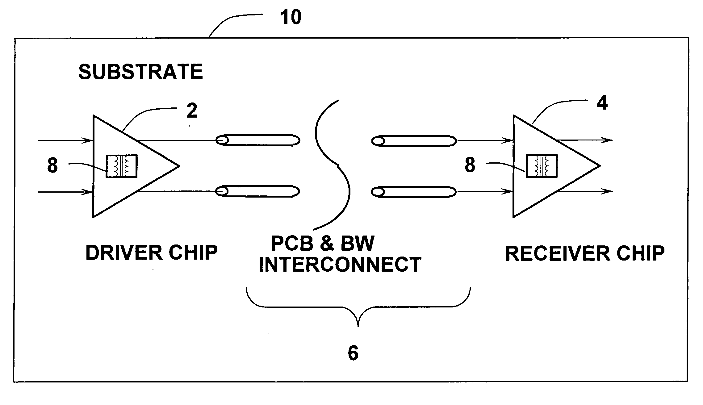
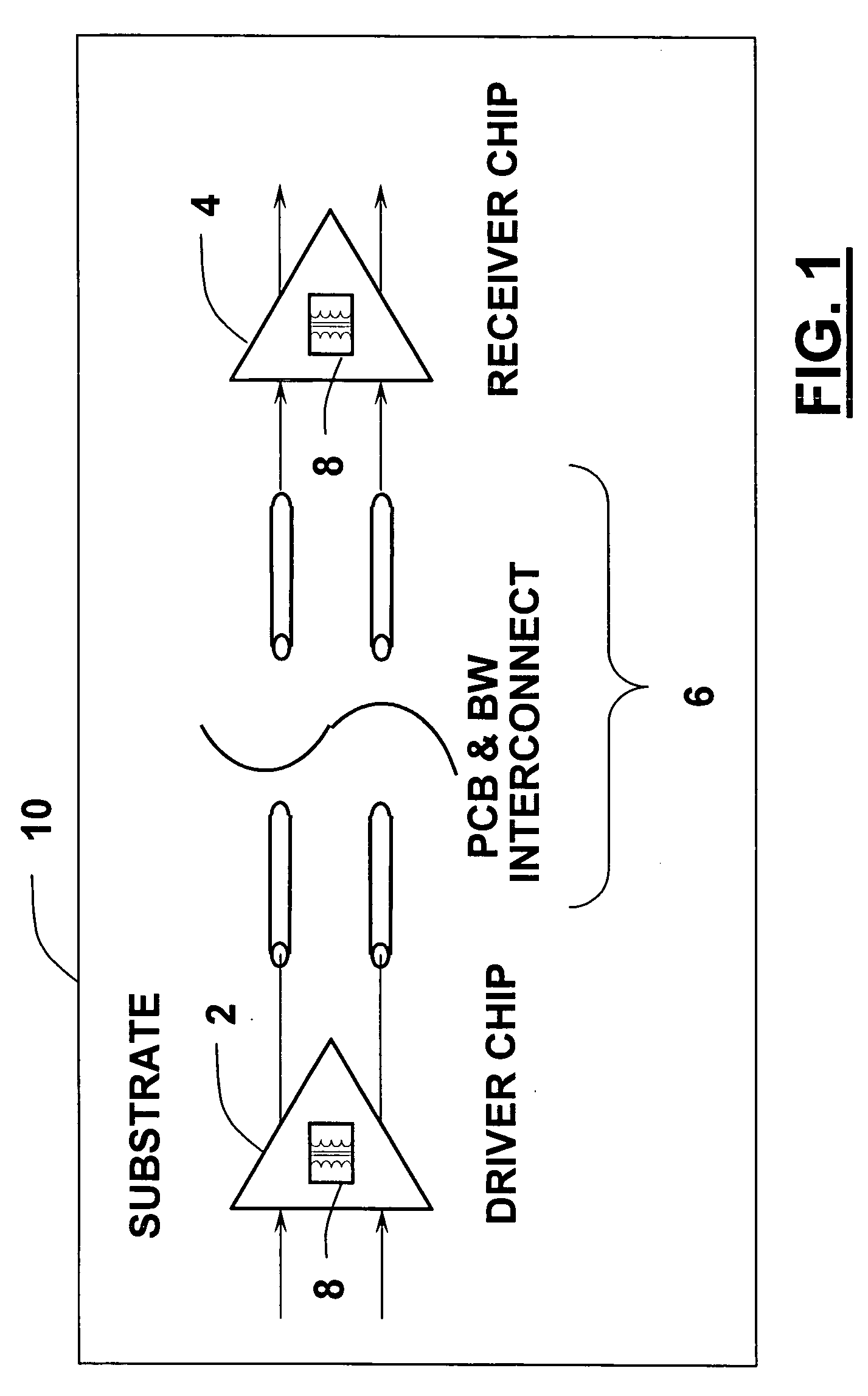
[0028]FIG. 1 illustrates a high level illustration of one embodiment of the present invention. In FIG. 1, a driver chip 2 includes a chip transformer 8 for isolating between the on-chip circuitry and the off chip circuitry. A receiver chip 4 also includes a chip transformer 8 for isolating between the on-chip circuitry and the off chip circuitry. An interconnect 6 is also shown which includes the printed circuit board (PCB) and bondwire connection between the driver chip 2 and the receiver chip 4. The driver chip 2 and receiver chip 4 are positioned on a substrate. Thus, it is shown that the present invention provides an ESD device that places a transformer at the transmitter and / or receiver as an interface and as an insulator between the chip internal circuitry and the PCB interconnect. The choice of including the ESD device at the transmitter and / or the receiver affects the encoding scheme of any signal transmitted across the ESD device. The ESD device can be used in RF circuits i...


PUM


Abstract

An integrated circuit for a high speed data communication system with improved Electrostatic Discharge (ESD) protection is provided. The circuit includes first and second monolithic transformers. An ESD device connected between the first and second monolithic transformers. There are first and second on-chip spark gaps for forming low impedance grounds during ESD events. The first on-chip spark gaps are electrically connected to the first monolithic transformer and the second on-chip spark gaps are electrically connected to the second monolithic transformer.

Description

PRIORITY STATEMENT [0001] This application claims priority to U.S. Provisional Patent Application No. 60 / 588,286, filed Jul. 15, 2004, herein incorporated by reference in its entirety.BACKGROUND OF THE INVENTION [0002] The present invention relates to chip design. More particularly, but not exclusively, the present invention relates to chip design that provides ESD protection and is suitable for use in high speed data communication systems. [0003] In recent years, much research has focused on improving high speed data communication systems especially in wireline data communication systems. The data rate can reach several Gbit / s. Several products offer around 3 Gbit / s data rate. There are several challenges that have to be met in order to increase the data rate to several Gbit / s. One of the challenges is the Electrostatic Discharge (ESD) protection devices that are placed at the driver and receiver to protect the chip from ESD events that can be devastating to the chip interior circu...

Claims


Application Information

Patent Timeline
Patent Type & Authority Applications(United States)
IPC IPC(8): H02H1/00
CPCH01T4/08
Inventor BADR, NADERBLACK, WILLIAM
Owner IOWA STATE UNIV RES FOUND
Why Eureka
Try Eureka