Scatter control system and method for computed tomography

a control system and computed tomography technology, applied in the field of computed tomography imaging systems, can solve the problems of image artifacts, degrade image quality, and pose limitations, and achieve the effects of reducing scatter in x-ray measurements, improving fidelity, and better dose utilization

Active Publication Date: 2006-02-02
GENERAL ELECTRIC CO
View PDF7 Cites 58 Cited by
  • Summary
  • Abstract
  • Description
  • Claims
  • Application Information

AI Technical Summary

Benefits of technology

[0009] The present invention provides novel techniques, which reduce scatter in X-ray measurements, provide better dose utilization, and provide projection data with improved fidelity. While presently contemplated applications for these systems include diagnostic medical imaging applications, the new techniques ...

Problems solved by technology

Though current CT imaging systems and SCT designs are very useful in identifying features of interest within a subject, they pose certain limitations.
The scatter component degrades image quality in resulting reconstructions.
Scatter in the measured data results in image artifacts and increases noise in the measurements, even if the scatter is accurately estimated and eliminated through special correction algorithms.
Scatter artifacts can be mitigated by subtracting an estimate of the scatter, but the signal to noise ratio (SNR) cannot be recovered by scatter correction.
As individual CT detectors sizes get smaller, a larger fraction of the area of each pixel is shadowed by the collimator blade, leading to poor dose utilization—a smaller amount of dose applied to the patient is detected and used for diagnostic imaging purposes.
The drawback ...

Method used


Image

  • Scatter control system and method for computed tomography
  • Scatter control system and method for computed tomography
  • Scatter control system and method for computed tomography

Examples


Embodiment Construction

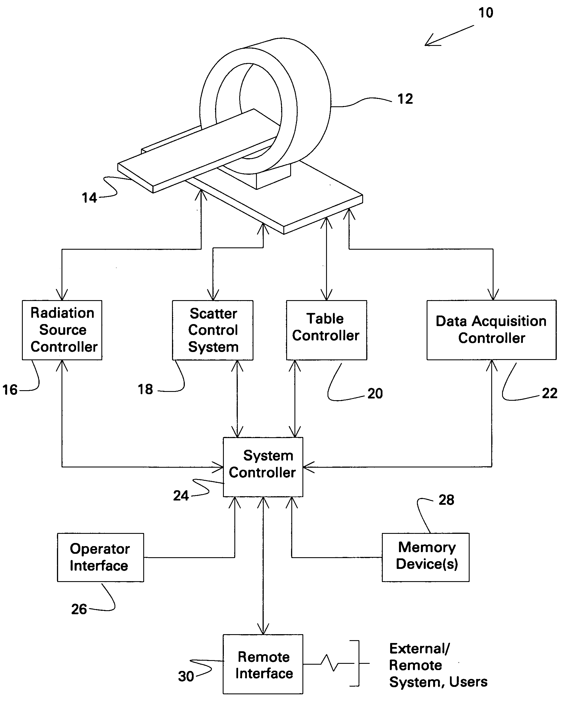
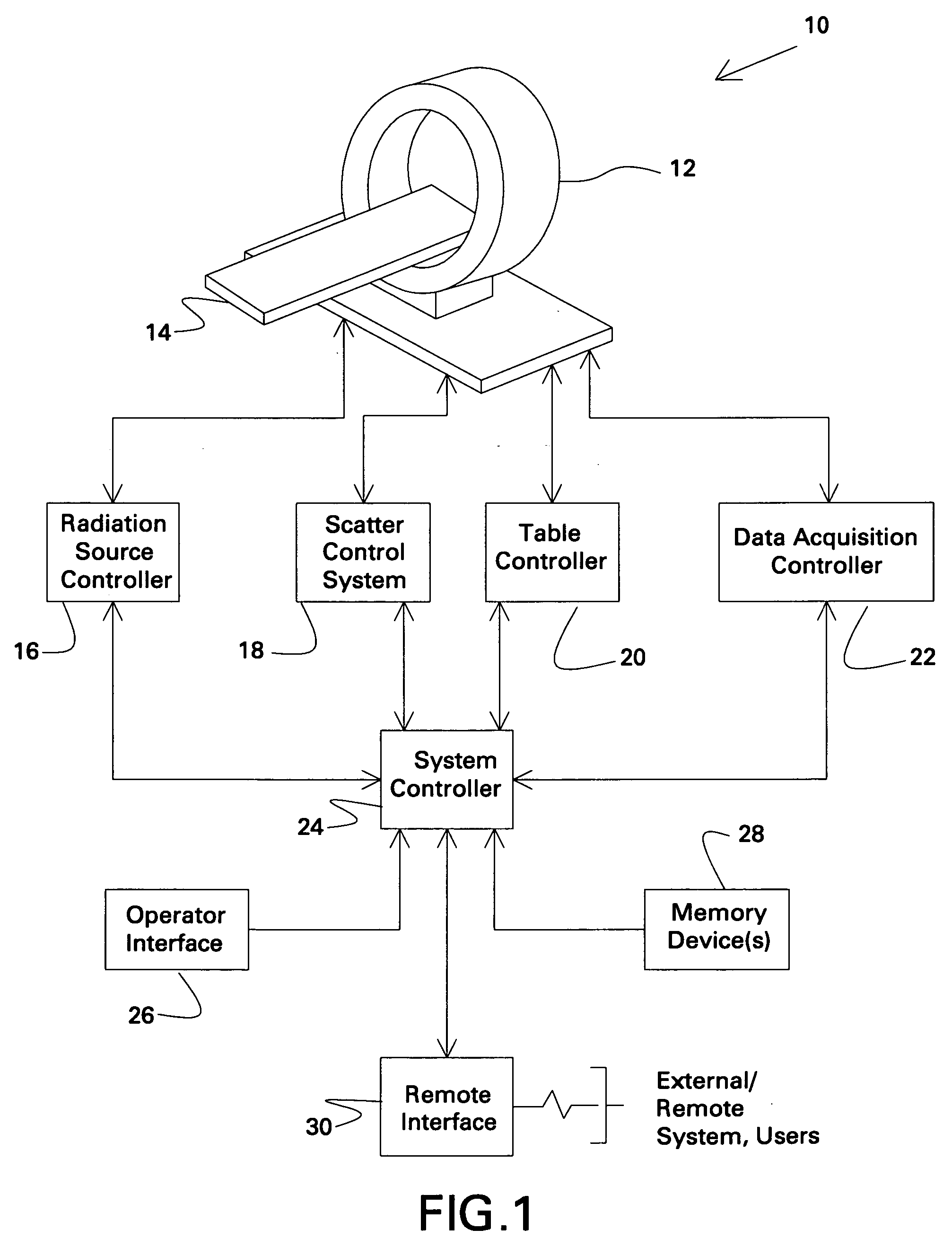
[0025] Turning now to the drawings, referring first to FIG. 1, a computed tomography (CT) system is illustrated and designated generally by reference numeral 10. The CT system 10 comprises a gantry 12 formed of a support structure and internally containing one or more stationary or rotational, distributed sources of an X-ray radiation (not shown in FIG. 1) and one or more stationary or rotational X-ray detectors (not shown in FIG. 1), as described in greater detail below. The gantry 12 is configured to receive a table 14 or other support for a patient (not shown), or, more generally, a subject to be scanned. The table can be moved through an aperture in the scanner to appropriately position the subject in an imaging volume or scanning plane during imaging sequences.

[0026] The system further includes a radiation source controller 16, a scatter control system 18, a table controller 20 and a data acquisition controller 22, which may all function under the direction of a system control...


PUM


Abstract

Various configurations for scatter reduction and control are provided for CT imaging. These configurations include an imaging system having a stationary detector extending generally around a portion of an imaging volume and a distributed X-ray source placed proximal to the stationary detector for radiating an X-ray beam toward the stationary detector. A scatter control system is further provided that is configured to adaptively operate in cooperation with the stationary detector and the distributed X-ray source to focally align collimator septa contained therein to the X-ray beam at a given focal point and to provide X-ray beam scatter control.

Description

BACKGROUND OF THE INVENTION [0001] The present invention relates generally to the field of computed tomography imaging systems. In particular, the invention relates to methods and systems for scatter control and reduction in a stationary computed tomography (SCT) system. [0002] Computed tomography (CT) imaging systems have been developed over the past decades and now are prolific in medical diagnostics and other contexts. In general, such systems typically include an X-ray source, such as a conventional X-ray tube, positioned diametrically opposed to an X-ray detector. In a so-called third generation CT system design, the source and detector rotate on a gantry, and the source is triggered repeatedly or is on continuously during rotation to produce beams of X-ray radiation that are directed through a subject of interest and fall onto the detector on the opposite side of a gantry. Features and structures of the subject attenuate the emitted radiation, and the detector measures the tra...

Claims


Application Information

Patent Timeline
IPC IPC(8): H05G1/60A61B6/00G01N23/00G21K1/12
CPCA61B6/032A61B6/4014A61B6/4291A61B6/5282G21K1/025A61B6/4028
Inventor EDIC, PETER MICHAELBERNARD DE MAN, BRUNO KRISTIAANVERMILYEA, MARK ERNESTUNGER, CHRISTOPHER DAVIDTKACZYK, JOHN ERICLEBLANC, JAMES WALTERBASU, SAMIT KUMARROSS, WILLIAM ROBERTSHORT, JONATHAN DAVIDZELAKIEWICZ, SCOTT STEPHEN
Owner GENERAL ELECTRIC CO
Why Eureka
Try Eureka