
Methods of sealing micro wells

a micro well and sealing technology, applied in the field of miniature instruments, can solve the problems of high electrical power required to operate the instrument, intrinsic limitations of the conventional instrument, and the inability to perform a large quantity of pcr with the conventional thermal cycler, and achieve the effect of simplifying laborious and expensive procedures

Inactive Publication Date: 2006-02-09
TAKARA BIO USA INC
View PDF53 Cites 25 Cited by
  • Summary
  • Abstract
  • Description
  • Claims
  • Application Information

AI Technical Summary

Benefits of technology

[0007] A principal aspect of the present invention is the design of miniaturized devices applicable for multiplex analyses of individual molecules, and / or simultaneous performance of a vast number of chemical reactions. The devices and methods of the present invention simplify the laborious and expensive procedures of performing chemical reactions where a control of the reaction temperature is desired or required.
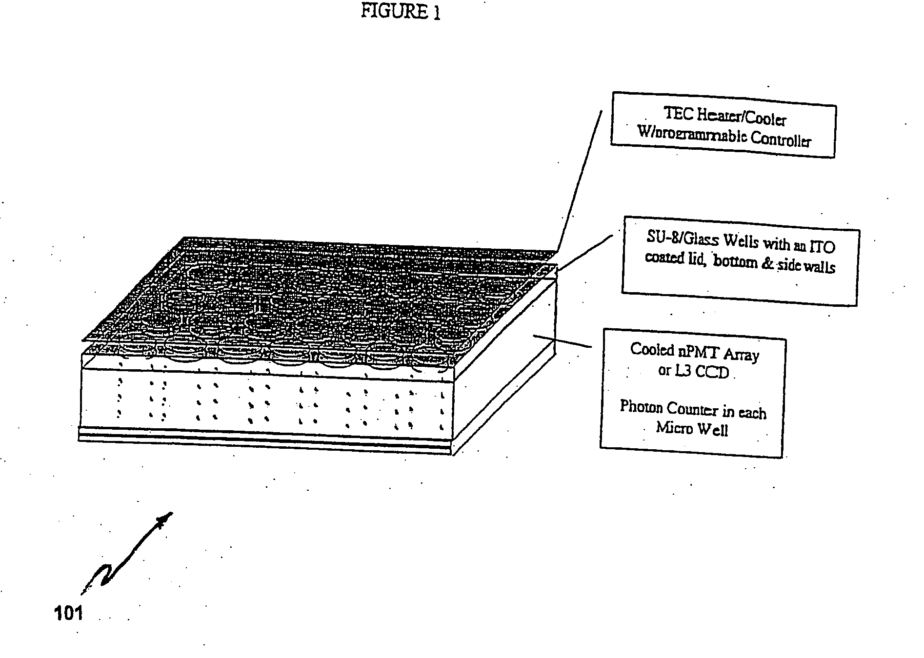
[0014] In other aspects, the thermo-controllable units of the subject chips can be arranged in different temperature zones, each of which can be separately controlled. In general, the micro well within each unit is in thermal contact with a heating element that can be made of metal or semi-conducting material. Preferred heating element is an indium-tin-oxide (ITO) heater. Heating element can be located within the micro well, or can be attached to the upper or bottom, or both surfaces of the micro well. To prevent evaporation and condensation of the reaction sample on the upper surface of the well, the upper surface can be maintained at a higher temperature than the bottom surface. In preferred embodiments, a plurality of grooves is fabricated to the bottom surface of the chip. The presence of the grooves greatly facilitates passive heat dissipation during thermal cycling. In other embodiments, the subject chips have a ramp temperature time about 10° C. or higher per second, preferably about 25° C. or higher per second. In other preferred embodiments, the subject chips may comprise temperature sensors in thermal contact with the micro wells.

Problems solved by technology

Performing a large quantity of PCR with the conventional thermal cycler has been rather expensive.
This is partly due to the intrinsic limitations of the conventional instrument.
Because the instrument has a large thermal mass and the plastic tubes have low heat conductivity, high level of electrical power is required to operate the instrument.
While the channel- or chamber-based design in principle-reduces the thermal mass and the reaction volume, it still suffers from other practical drawbacks.
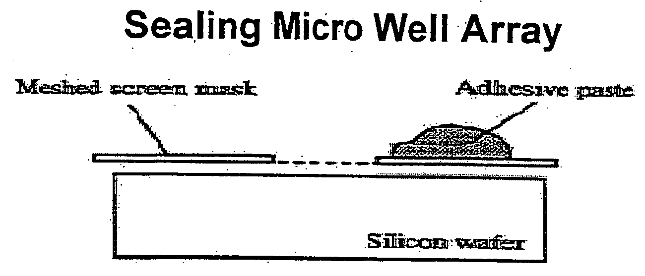
In particular, the channels or chambers by design are not amenable to automated sealing that prevents evaporation and / or cross contamination of the reaction samples.

Method used


Image

  • Methods of sealing micro wells
  • Methods of sealing micro wells
  • Methods of sealing micro wells

Examples


example 1

[0143] Amplification of a target nucleic acid, namely a fragment of the G6PDH gene, is performed using a chip of the present invention. The reaction mixture containes G6PDH template, a pair of upstream and downstream primers specific for the template, dNTPs, and DNA polymerase.

[0144] The amplified products are detected with SYBR Green I that binds preferentially to double-stranded DNA molecules (see, FIG. 20). FIG. 21 depicts the SYBR Green staining of DNA molecules appeared at the three different thermal stages of one PCR cycle. As is shown in FIG. 21, staining of the DNA is most intense at the annealing step (e.g., at 45° C.) because most of the DNA molecules assume a double helical structure. By contrast, very little SYBR Green staining is detected at the denaturing step where the temperature is raised to e.g., 95° C. At about 72° C. where primer-directed extension is taking place, a moderate amount of staining is detected. The amount of SYBR Green stain detected throughout one ...


PUM

PropertyMeasurementUnit
Electrical conductoraaaaaaaaaa

Abstract

The present invention provides miniaturized instruments for conducting chemical reactions where control of the reaction temperature is desired or required. Specifically, this invention provides chips and optical systems for performing and monitoring temperature-dependent chemical reactions. The apparatus and methods embodied in the present invention are particularly useful for high-throughput and low-cost amplification of nucleic acids.

Description

CROSS-REFERENCE TO RELATED APPLICATIONS [0001] This application claims the priority benefit of U.S. Provisional Application Ser. No. 60 / 630,789 filed Nov. 24, 2004, and U.S. patent application Ser. No. 10 / 857,552 filed May 28, 2004, all of which are hereby incorporated herein by reference in their entirety.TECHNICAL FIELD [0002] This invention relates to miniaturized instruments for conducting chemical reactions where control of the reaction temperature is desired or required. Specifically, the invention relates to chips and optical systems for performing temperature-dependent chemical reactions. The apparatus and methods embodied in the present invention are particularly useful for high-throughput and low-cost amplification of nucleic acids. BACKGROUND OF THE INVENTION [0003] The advent of Polymerase Chain Reaction (PCR) since 1983 has revolutionized molecular biology through vastly extending the capability to identify, manipulate, and reproduce DNA. Nowadays PCR is routinely pract...

Claims


Application Information

Patent Timeline
IPC IPC(8): B32B37/00B01L3/00B01L7/00C12M1/00G01N21/03G01N21/25G01N21/64G01N21/76G01N35/00G01N35/04
CPCB01L3/50851B01L3/50853G01N2035/0405B01L7/52B01L7/54B01L2200/0689B01L2300/044B01L2300/0636B01L2300/0654B01L2300/0819B01L2300/1822B01L2300/1827B82Y30/00C12Q1/6844G01N21/0332G01N21/6408G01N21/6452G01N21/76G01N35/0099G01N2021/6417G01N2021/6484C12Q2565/501H01L27/1443B01L2300/0829B01L2300/18C12Q1/6806C12Q1/686G01N21/01G01N2201/0231H01L31/0203H01L31/02325H01L31/024H01L31/105H01L31/18
Inventor JOSEPH, VICTORHUDA, AMJADSHIVJI, ALNOORZHOU, JIE
Owner TAKARA BIO USA INC
Learn More