Remote current sensor monitoring system and GPS tracking system and method for mechanized irrigation systems

Active Publication Date: 2006-02-09
HAALAND KARLYLE
View PDF6 Cites 149 Cited by
  • Summary
  • Abstract
  • Description
  • Claims
  • Application Information

AI Technical Summary

Benefits of technology

[0026] It is an object of the present invention to provide a safe and simplified installation and an improved method to remotely monitor center pivot running status (on or off, wet or dry, and pivot arm position, direction, speed of travel and rate of water application) with improved reliability and lowered cost.
[0027

Problems solved by technology

Factors such as soil type, soil water intake rate, slope, water availability, energy costs, flotation for wheels and land obstacles affect the use of such systems.
An unnoticed shutdown may result in substantial loss of the crop.
Such applications typically take three to four days to complete and longer for larger fields.
Unplanned stoppages are common due to field conditions (stuck wheels) and mechanical and electrical malfunction (broken drive lines, failed electro-mechanical devices, etc.).
Water delivery systems also breakdown and cause irrigation systems to stop.
Electrical power outages and deliberate load shed schemes by power providers can cause hundreds of irrigation systems to shutdown at any hour of the day.
Water delivery systems powered by natural gas engines are subjec

Method used


Image

  • Remote current sensor monitoring system and GPS tracking system and method for mechanized irrigation systems
  • Remote current sensor monitoring system and GPS tracking system and method for mechanized irrigation systems
  • Remote current sensor monitoring system and GPS tracking system and method for mechanized irrigation systems

Examples


Embodiment Construction

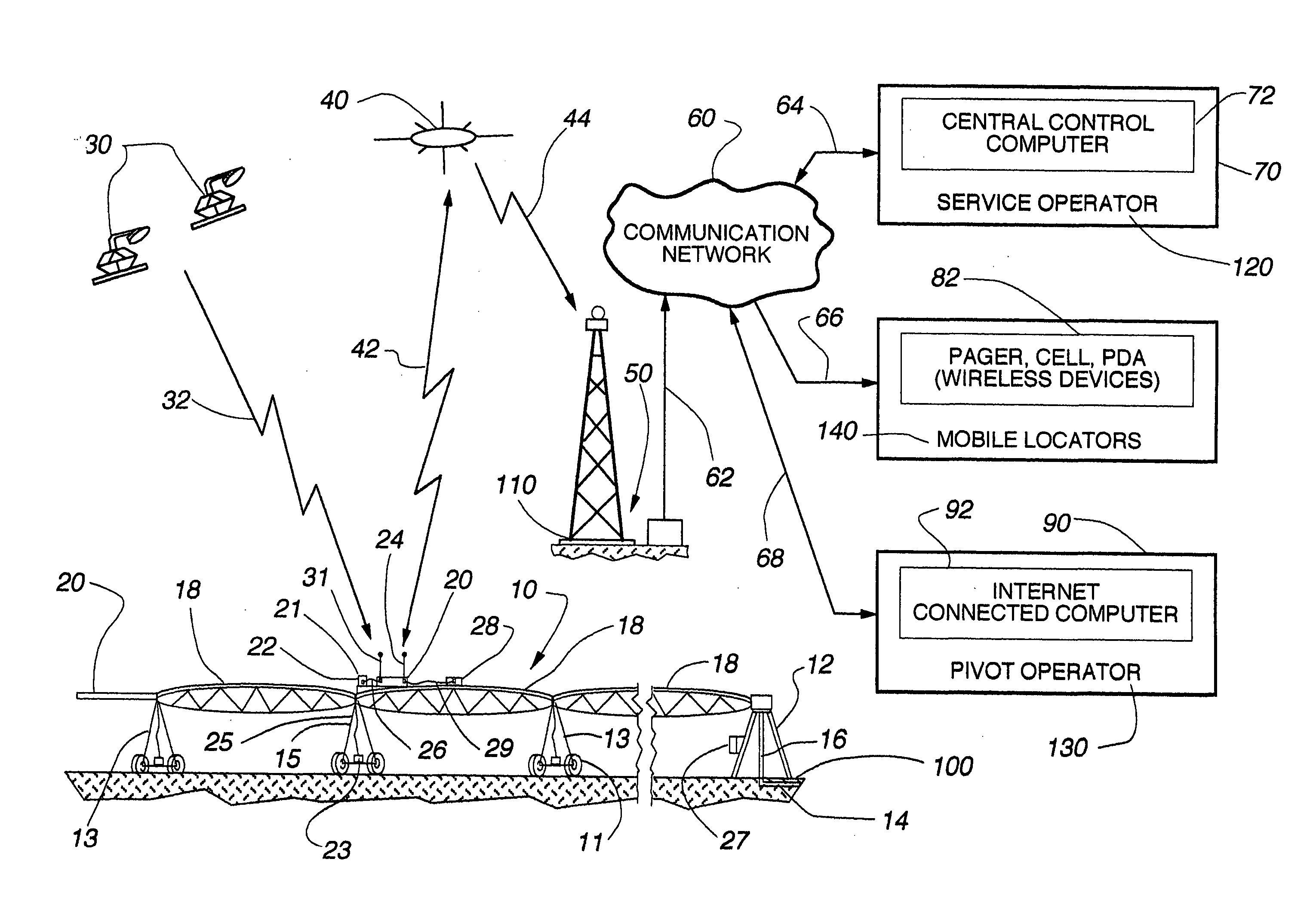
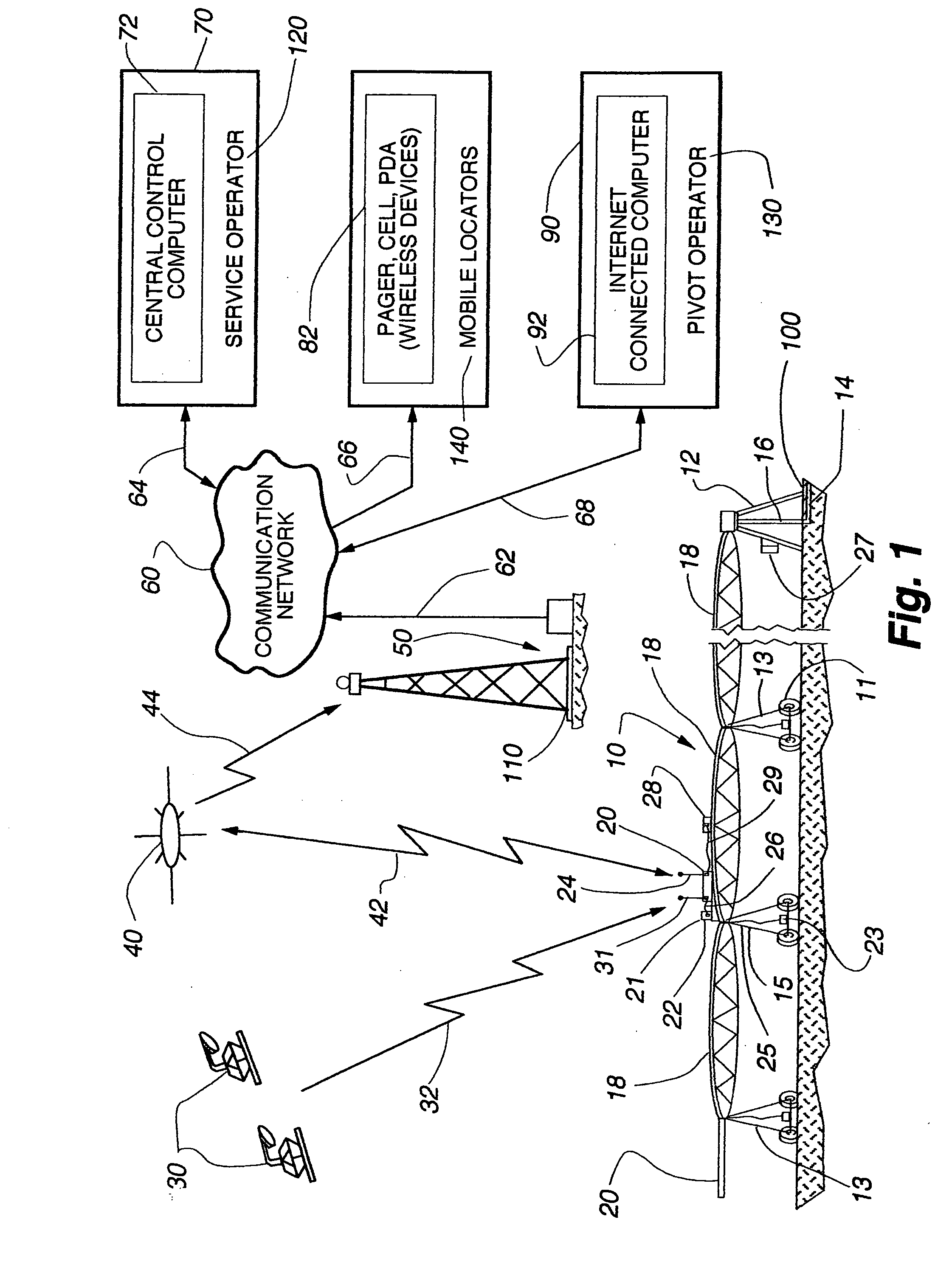
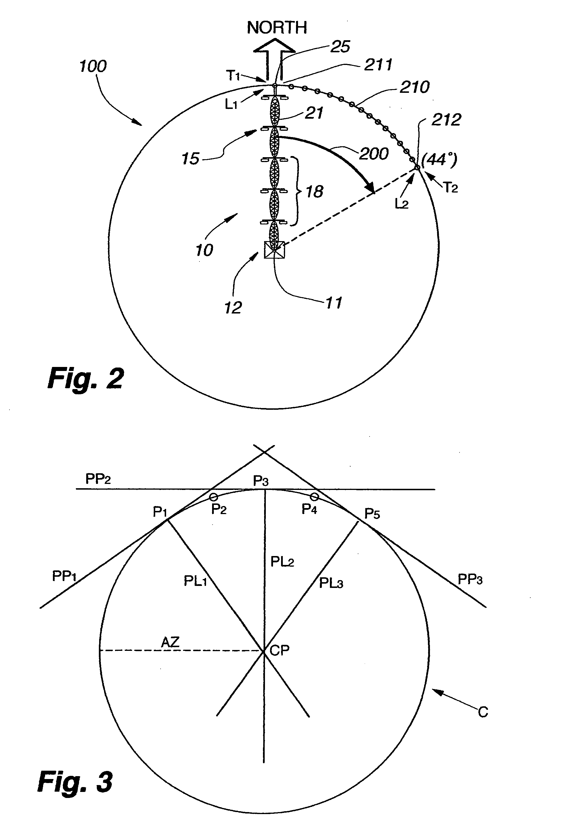
[0056] The system of the present invention is illustrated in FIG. 1 as being connected to a center pivot or lateral mechanized irrigation system 10 (herein sometimes simply referred to as “pivot” or “center pivot”). The invention includes a universal, self-contained remote terminal unit (RTU) with global position satellite (GPS) receiver 20 which receives signals from GPS positioning satellites 30. The remote terminal unit is further connected to a low orbit data communication satellite 40, a ground station 50, a communication network 60, a service operator location 120, multiple mobile locations 140, and a remote pivot operator monitoring location 130.

[0057] Mechanized irrigation systems 10 are conventional and commercially available from a number of different manufacturers. Mechanized irrigation systems 10 are commonly used in a center pivot configuration such as shown in FIG. 1 wherein the center pivot point 12 extracts pressurized water 14 for delivery through a fluid delivery ...


PUM


Abstract

A wireless interface remote monitoring system for self-propelled irrigation systems (center pivot and lateral move sprinklers) includes a remote terminal unit (RTU) mounted on an outer drive tower of the irrigation system. The RTU includes a radio transceiver capable of sending and receiving data packets over a satellite or terrestrial telemetry backbone to and from a central control computer. The RTU further includes a current sensor and a GPS receiver both for detecting movement or non-movement of the sprinkler, a microprocessor with nonvolatile memory for storing current data and GPS coordinate data from readings taken in series over time, and a pressure or flow sensor for detecting the presence or absence of water flow at the outer drive tower of the sprinkler. The current sensor connected between the RTU and a tower drive motor, allows the RTU to calculate the “movement” or “non-movement” of the irrigation system over a specified time period. Redundantly, the GPS receiver records changes in position to indicate movement or non-movement within the GPS error tolerance. Once a change from movement to non-movement or vice-versa is determined, the RTU transmits the data by satellite or radio telemetry to a central control computer which logs the movement or non-movement of the monitored drive tower, the GPS coordinate data and the water status readings, all with time and date stamp. The central control computer creates “page message” and “text message” updates as necessary on the status of individual irrigation systems and “groups” of irrigation systems that are in turn delivered to wireless devices and computers for sprinkler operators.

Description

RELATED APPLICATIONS [0001] This application claims the benefit of U.S. Provisional Patent Application Ser. No. 60 / 598,950 filed Aug. 5, 2004; U.S. Provisional Patent Application Ser. No. 60 / 613,773 filed Sep. 28, 2004 and U.S. Provisional Patent Application Ser. No. 60 / 695,076 filed Jun. 29, 2005.BACKGROUND OF THE INVENTION [0002] 1. Field of the Invention [0003] The present invention relates generally to center pivot and lateral move irrigation systems. More specifically, the present invention relates to a remote monitoring unit which senses movement or non-movement of the irrigation system over a span of time to determine operating status (running or stopped), to determine pivot arm position (e.g., location of last wheel set) and to remotely sense water delivery through the span pipes to determine wet / dry status. The remote monitoring unit is self-contained without having to hard-wire directly to any existing control or other electrical circuits of the irrigation system. [0004] 2...

Claims


Application Information

Patent Timeline
IPC IPC(8): A01G27/00
CPCA01G25/16A01G25/092
Inventor ABTS, GERALD L.
Owner HAALAND KARLYLE
Why Eureka
Try Eureka