
Termite acoustic detection

Inactive Publication Date: 2006-02-09
UNIVERSITY OF MISSISSIPPI
View PDF38 Cites 84 Cited by
  • Summary
  • Abstract
  • Description
  • Claims
  • Application Information

AI Technical Summary

Benefits of technology

[0032] It is, accordingly, a first advantage of the invention that a nondestructive and yet reliable method and apparatus for accurately detecting the presence of termites very quickly is provided.
[0033] It is a second advantage of the invention that a termite detection method that utilizes nondestructive acoustic detection, that is carried out in the full termite noise frequency range of 100 Hz to 15 KHz, and that does not require on-site monitoring or interpretation of the acoustic detection results by a human operator is provided.
[0034] It is a third advantage of the invention that a termite detection method that utilizes nondestructive acoustic detection and yet that minimizes the number of acoustic sensors, sample sites and time required to inspect a structure is provided.
[0035] It is a fourth advantage of the invention that a central database of termite information, made available to appropriate entries and individuals, is provided.
[0036] The acoustic detection system of the present invention enables the detection of termite infestation in buildings and trees accurately and as early as possible. Early and accurate detection of an infestation reduces damage and the resultant amount of insecticide use required to stop it. By using acoustic detection, little to no damage to buildings or trees occurs during the inspection process, therefore reducing the amount of money spent by the homeowner on repair work as well as reducing the risk of a lawsuit by the homeowner.
[0037] This invention further relates to the use of a laser doppler vibrometer to detect vibration of an unexcited wall, tree or other concealing structure. In particular, this invention involves use of a laser Doppler vibrometer to detect acoustic patterns following acoustic excitation of the structure being evaluated, using apparatus and techniques similar to those described in detail in U.S. Pat. No. 6,081,481, herein incorporated by reference.

Problems solved by technology

Termites are extremely destructive to wood material.
It is difficult to put a dollar amount estimate on termite damage.
Untreated foundations make the house very susceptible to termite attack.
It is often very difficult and costly to apply effective control measures after a building has become infested with termites.
It is rarely apparent from visual observation that a termite infestation is active and that wood damage is occurring.
This method has significant disadvantages.
Also, when termites are exposed in this manner, the destruction induces termites to retreat from the disturbed area and may reduce the effectiveness of a subsequent localized treatment.
However, none of these techniques has satisfied the non-destructive and non-subjective requirements, and many infestations are still missed.
A significant disadvantage, however, is that the gases must be abstracted within a confined space, such as within the walls of a structure.
These devices are thus unsuitable for detecting termites in wood that is not within a confined space.
Moreover, the use of these devices to detect termites is very time-consuming and costly as a result.
The ultrasonic frequencies, however, are difficult to detect through walls and other concealing structures due to the signal's very short distance of travel (ultrasonic frequencies have very high transmission loss), and this process fails to take into account the full range of termites noises, which fall primarily in the range of 100 Hz to 15 kHz.
These devices require a high degree of operator skill.
In addition, such devices typically use a relatively narrow frequency range.
The '356 patent, however, fails to disclose specific apparatus, algorithms or noise patterns useful for detection over the specified frequency range.
The various devices for sensing the destruction of bait sample are useful for detecting the presence of termites in the vicinity of a structure, but cannot be used to locate precise areas of termite infestation in concealed areas within the structure.
Once it has been determined that termites are present in the vicinity of the structure, the only way to determine the actual locations of termites within the structure is to remove portions of the structure, which is, again, damaging and costly.
However, this is a relatively nonspecific method, yielding many, many false positives since there are many sources of temperature differences in a typical structure, such as non-uniform insulation material, air-conditioning ducts, leakage, air movement through wall cracks, water and moisture problems, etc.
As a result, detection of termites using infrared sensors still requires destruction of walls to verify results and to more specifically locate the actual termite infestations.
Furthermore, use of infrared sensing for detection of termites also requires a relatively high degree of operator skill, training and judgment which adds time and cost to its use.
Such devices, however, generally do not take into account the full range of termite sounds, as explained above.
Moreover, the design of prior devices has generally resulted in only highly localized detection ability, thereby necessitating the taking of many samples or data points, and requiring an inordinate amount of time or number of sensors to completely inspect a structure.
As a result of the various practical difficulties outlined above, the prior devices described above have generally seen insignificant commercial implementation despite the long-felt need for nondestructive termite and wood-destroying insect detection.

Method used


Image

  • Termite acoustic detection
  • Termite acoustic detection
  • Termite acoustic detection

Examples


Embodiment Construction

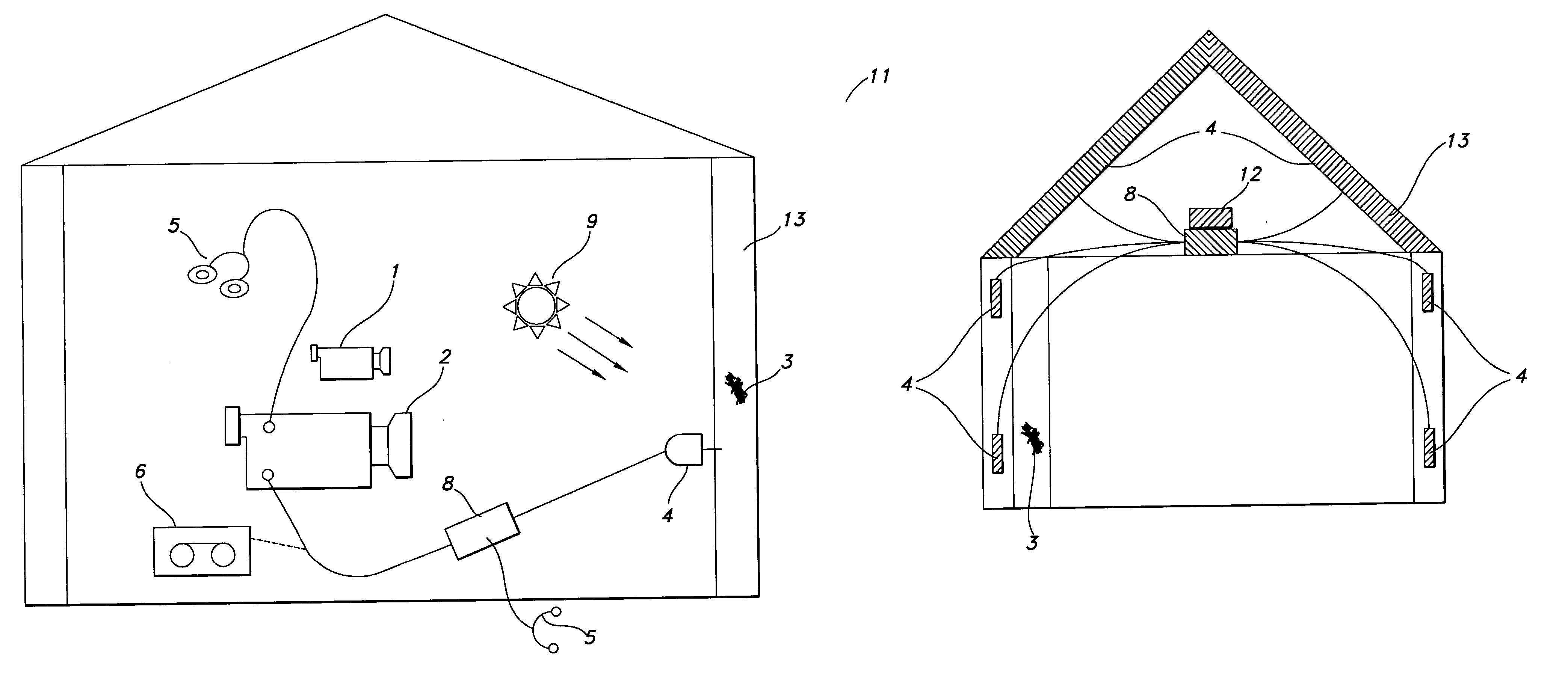
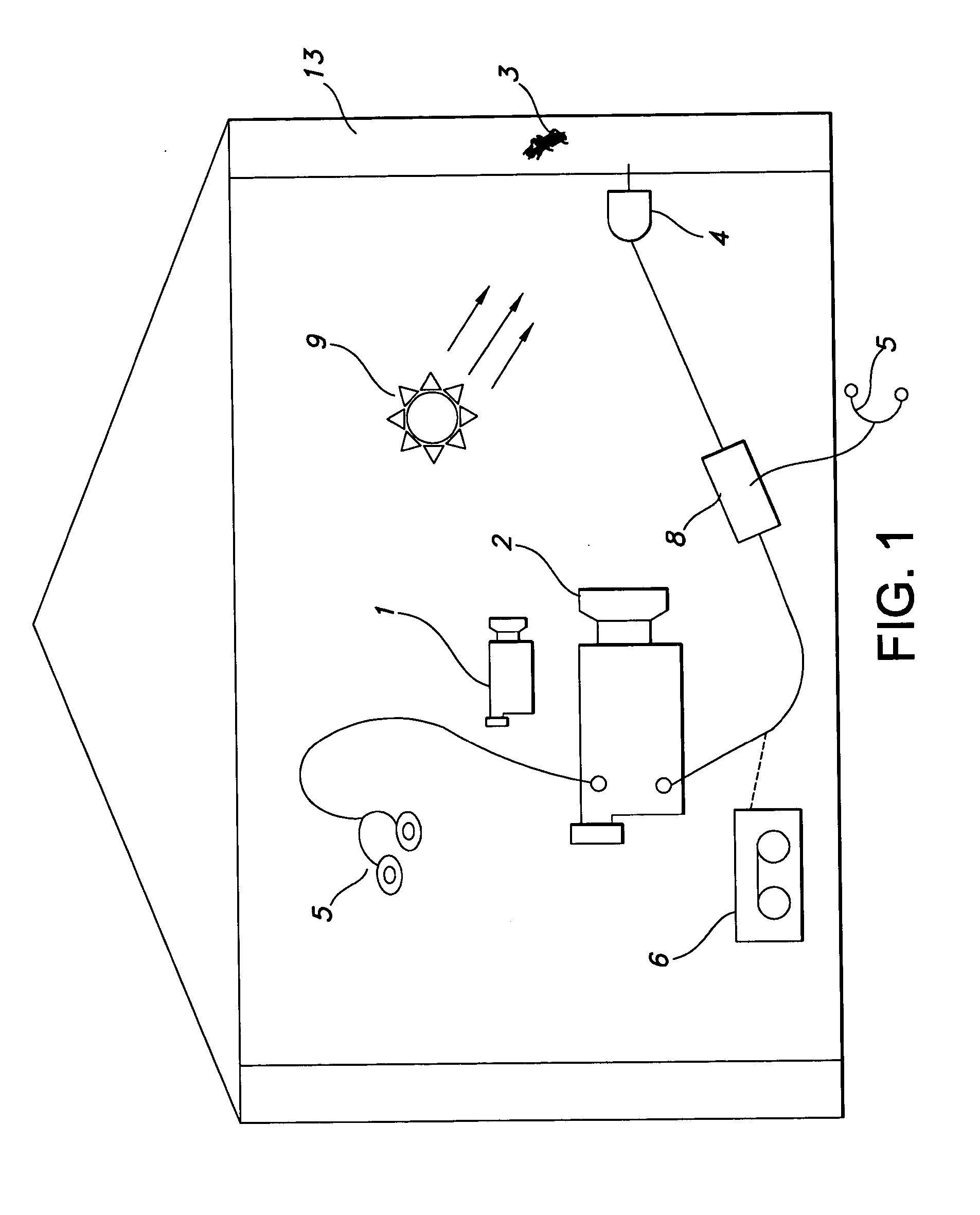
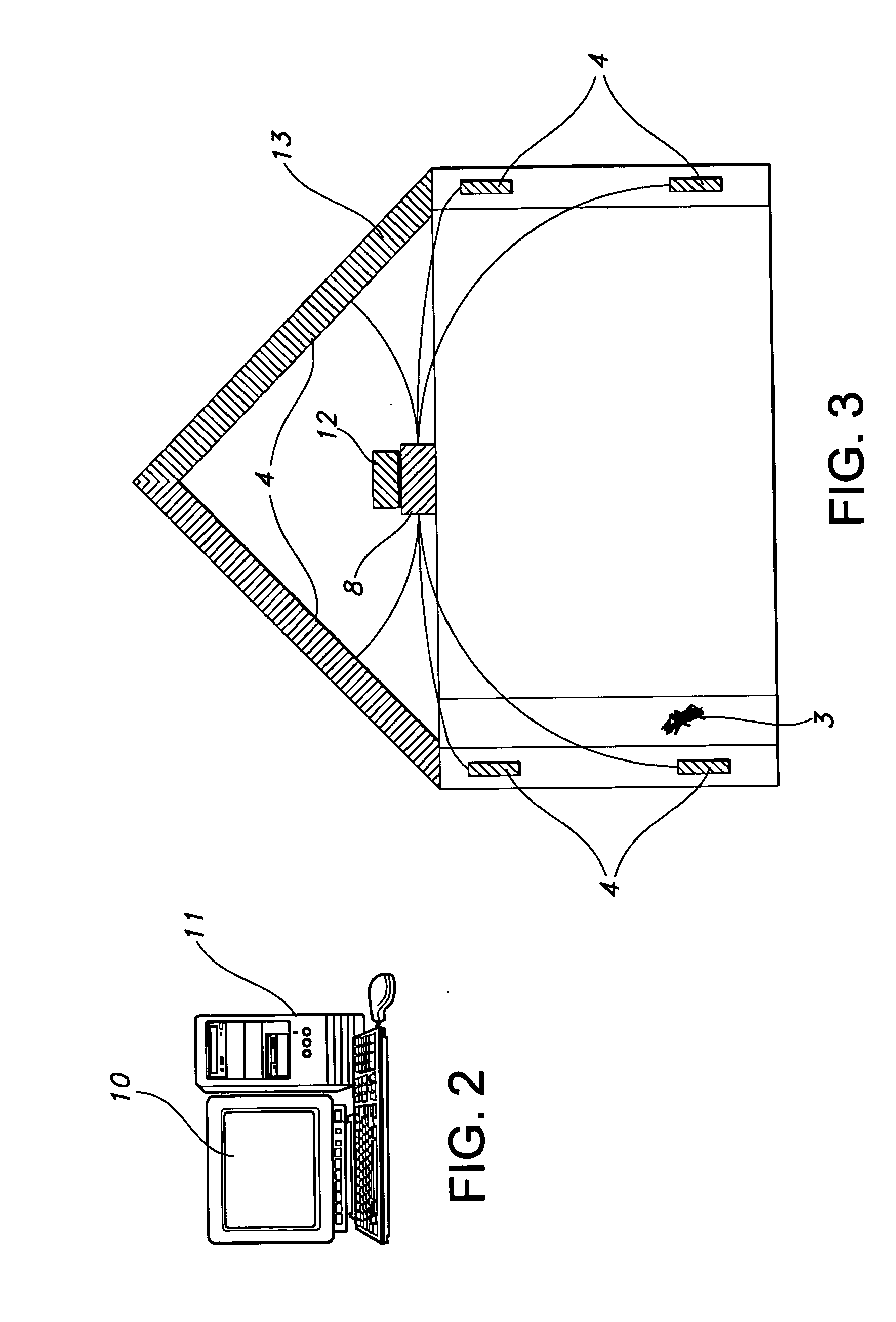
[0049] As schematically depicted in FIG. 1, a preferred embodiment of the apparatus and method of the present invention includes a thermal imaging camera 1 for performing a preliminary scan of a structure 13 in order to locate potential termite infestations sites 3. The structure 13 can be a wooden object, such as a wall stud, paneling or in one embodiment a live tree. Termite infestation sites 3 can be the result of subterranean termite or dry-wood termite activity. In the case of a subterranean termite infestation, the moisture brought in by the subterranean termites will show up as a “suspicious cold or hot spot” in a thermal imaging scan. In the case of a dry-wood termite infestation, a heat or cold source 9 is needed to increase or decrease the temperature of a targeted structure 13. This heat source 9 can be an electric, gas or oil heat source as well as an incandescent or infrared light source. The areas in the targeted structure 13 that contain a cavity created by dry-wood t...


PUM


Abstract

A method and system for detecting the presence of subterranean termites, involving use of a thermal imaging camera to scan the structure before installation of an acoustic sensor in order to quickly locate potential areas of subterranean termite infestation, and an acoustic sensor in the form of an accelerometer or the disclosed innovative acoustic sensors having a bandwidth of at least 100 Hz to 15 kHz to detect noises made by the subterranean termites. Information collected by the acoustic sensor may be transmitted to a portable mini-computer (pocket PC) for confirmation and to a central operations center for inclusion in a comprehensive database of termite data and information. A method and system for detecting the presence of dry-wood termites concealed in a structure, involving use of a heat source to warm up the wooden structure of interest and then using a thermal imaging camera to scan the structure for suspicious dry-wood infestation, followed by the use of an acoustic sensor and pattern recognition software to more precisely and accurately locate potential area of dry-wood termite infestation. Additionally, structural damage can be evaluated by the methods discussed herein, including live trees. Additionally, the method can be used to manipulate termite infestation behavior.

Description

RELATED APPLICATIONS [0001] This application is a continuation-in-part and claims the benefit under 35 U.S.C. § 119(e) of U.S. Provisional Application Ser. No. 60 / 417,257 filed Oct. 9, 2002, hereby specifically incorporated by reference in its entiretySTATEMENT REGARDING FEDERALLY SPONSORED RESEARCH OR DEVELOPMENT [0002] Not applicable REFERENCE TO APPENDIX [0003] The computer program listing appendix submitted on a compact disk is hereby incorporated by reference. Two duplicate copies of a single disk are included. The disk was made on Oct. 4, 2003. FIELD OF THE INVENTION [0004] This invention relates to insect detection and, more particularly, to methods, systems and devices for detecting and preventing termite damage. DESCRIPTION OF RELATED ART [0005] Termites are extremely destructive to wood material. Termites attack and destroy wood almost everywhere in the world, with the exception of climate zones that experience hard freezing. There are close to fifty species of termites in...

Claims


Application Information

Patent Timeline
IPC IPC(8): G08B23/00A01M1/20
CPCA01M1/24A01M1/026
Inventor LEE, PENG
Owner UNIVERSITY OF MISSISSIPPI
Learn More