
Dissemination system for satellite broadcasting

Inactive Publication Date: 2006-02-09
SMSC EURO
View PDF9 Cites 39 Cited by
  • Summary
  • Abstract
  • Description
  • Claims
  • Application Information

AI Technical Summary

Benefits of technology

[0006] The invention is based on the object of designing a distribution system for satellite broadcasting which is not attended by the above-mentioned disadvantages, and is suitable for a simultaneous connection of a large number of subscribers with high flexibility and at low cost.
[0015] Another embodiment of the invention relates to the design of the bus system as a digital bus system. As a rule, bidirectional communication is possible in bus systems of this kind. Therefore it is particularly easy for the subscribers to inform an associated receiver of the channel of the satellite band it is to receive and demodulate. Similarly, a series of additional communication possibilities exist via the bus system. Thus, for example, further parameters such those concerning signal quality or other information such as the time of day may be transmitted. Furthermore, with a bus system of this kind an intelligent control may be effected. If, for example, two or more subscribers request the same channel, then it is now possible to notify these subscribers of the receiver that is presently demodulating this channel, or of the data stream in which the desired packages are to be found. Thus, a multiple demodulation of the same channel by a plurality of receivers is dispensed with. This is of particular advantage with large systems, because here there is a high probability of at least some subscribers requesting the same channel. Thus, the number of receivers may be chosen to be smaller than the number of subscribers. This leads to a further saving of cost.
[0016] Furthermore, the bus system may be employed not only for disseminating the satellite signals, but additionally also for data transmission, such as, for example, in PC networks, or for building automation. Thereby it becomes only still necessary to provide a single network infrastructure that will cope with all possible communication tasks in a building. In comparison with known solutions having a plurality of network or cable systems, this leads to an enormous saving of cost.
[0018] Furthermore, in an advantageous manner the subscribers may be designed at particularly favorable cost, because they now require only standard decoders, such as MPEG decoders, for example. Thus, simple MPEG decoders which, for example, may be embodied in PCs by means of software, or are in any case integrated in DVD players, may be employed in place of customary satellite receivers that require much outlay. This leads to a strong reduction of the cost of the entire system.
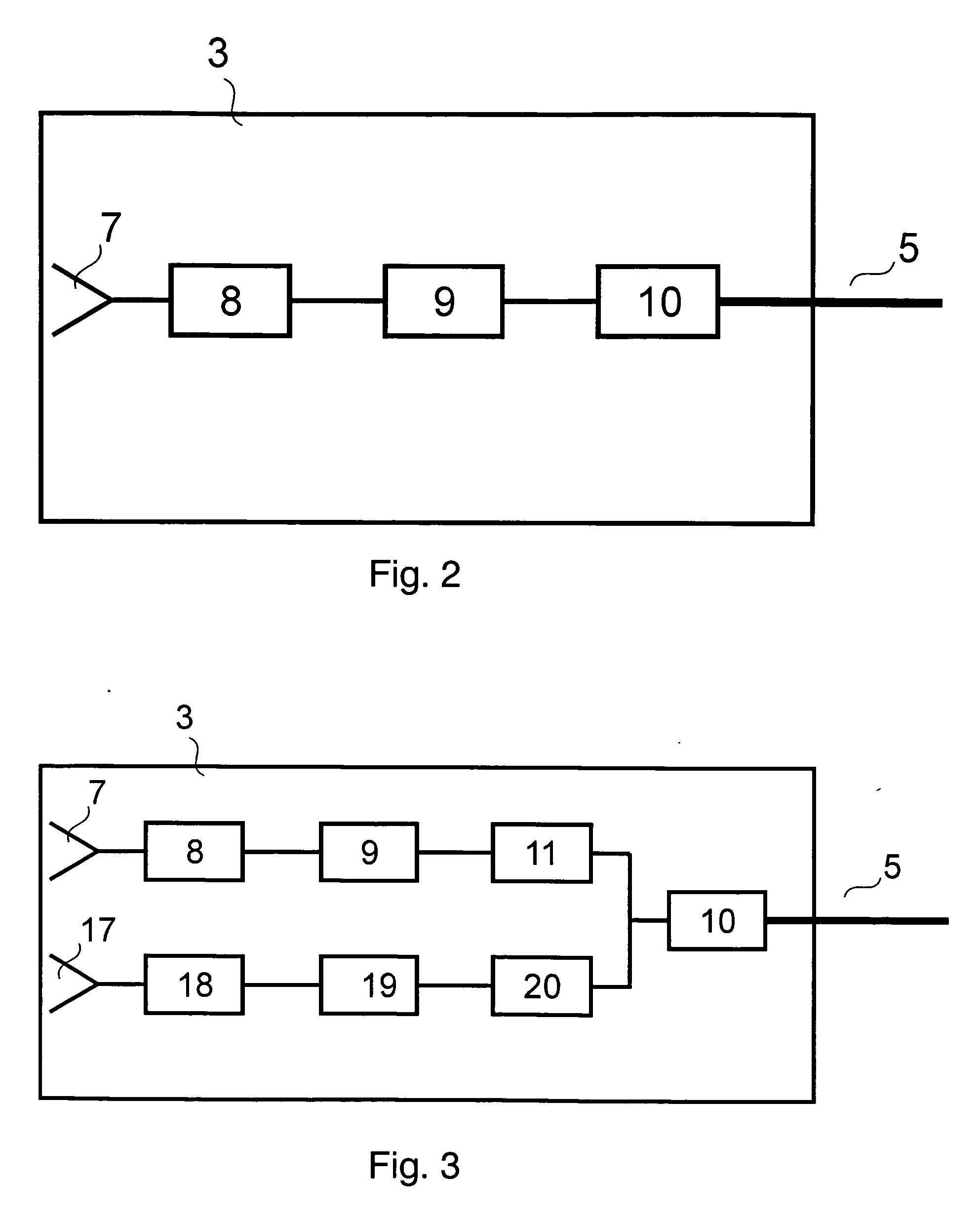
[0019] Another embodiment of the invention provides at least one diversity unit which filters out from the signals of a plurality of receivers, and transmits to the subscribers, the particular signal that has the best quality. The filtering may be effected optionally by using the demodulated signals of receivers, or also by using digital signals which are transmitted via a bus. It is particularly easy to select the best channel when a receiver, during real-time encoding of the signals, computes a quality parameter and transmits this to the diversity unit. Thus, using this parameter, the diversity unit may perform a simple selection of the best channel.

Problems solved by technology

The problem with arrangements of this kind is that the bandwidth available with conventional cable systems is far less than adequate for distributing all transmittable channels, particularly with simultaneous reception from a plurality of satellites.
The disadvantage of a solution of this kind is the high complexity of the terminal station, attended by low flexibility.
This system has the disadvantages of an extremely high complexity, a high outlay of optical components, and at the same time a low transmission quality by optical signal transmission in the base band.
The disadvantage of this arrangement consists of a low transmission quality owing to the optical signal transmission in the base band.

Method used


Image

  • Dissemination system for satellite broadcasting
  • Dissemination system for satellite broadcasting
  • Dissemination system for satellite broadcasting

Examples


Embodiment Construction

[0006] The invention is based on the object of designing a distribution system for satellite broadcasting which is not attended by the above-mentioned disadvantages, and is suitable for a simultaneous connection of a large number of subscribers with high flexibility and at low cost.

[0007] An achievement of this object in accordance with the invention is set out in the independent patent claims. Further developments of the invention are the subject matter of the dependent claims.

[0008] In the following, reference will be made exclusively to the concept of satellite broadcasting for reasons of clarity of presentation. This includes services such as satellite TV and satellite radio, in analog and digital form, and also purely digital services such as a distribution of internet data via satellite channels.

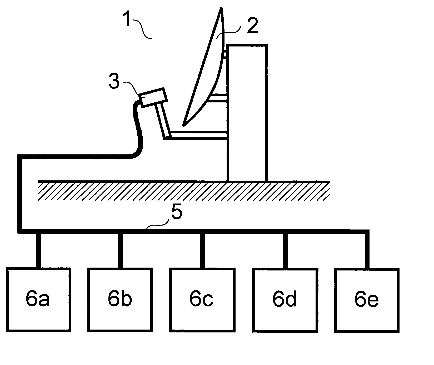
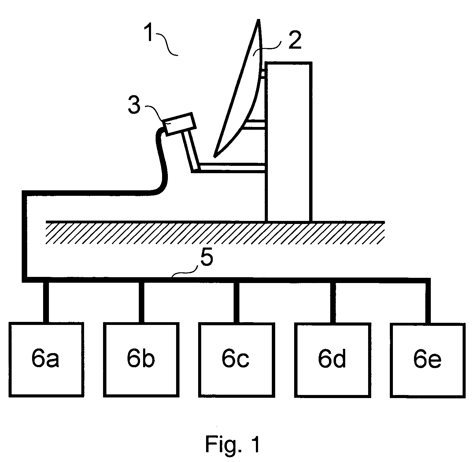
[0009] A dissemination system in accordance with the invention comprises at least one satellite receiving antenna for receiving the satellite signals, at least one LNB (Low Noise Bl...


PUM


Abstract

A dissemination system for satellite broadcasting comprises a satellite receiving antenna for receiving satellite signals, receivers for demodulating the signals received by the antenna, and a line system for distributing the signals to a plurality of subscribers, in which the receivers are assigned to the satellite receiving antenna in close spatial proximity, and only demodulated or decoded signals are relayed to the subscribers by means of the line system.

Description

TECHNICAL FIELD [0001] The invention relates to a dissemination system for satellite broadcasting and related services. PRIOR ART [0002] Conventional dissemination systems for satellite broadcasting, as described for example in U.S. Pat. No. 5,787,335, are based on distributing analog high frequency signals by means of coaxial cables. Two cable strands are employed for a simultaneous transmission of signals having two polarizations. Here an improvement is indicated by U.S. Pat. No. 5,805,975, in which signals of a second polarization are converted to a different frequency region. For this, however, a substantially more broadband cable, and also a more broadband distribution system are needed. The problem with arrangements of this kind is that the bandwidth available with conventional cable systems is far less than adequate for distributing all transmittable channels, particularly with simultaneous reception from a plurality of satellites. [0003] Here an improvement is provided by re...

Claims


Application Information

Patent Timeline
IPC IPC(8): H04H1/00H04H40/90H04N7/20
CPCH04N7/20H04H40/90
Inventor HETZEL, HERBERTKLOS, RAINERHECK, PATRICKTHIEL, CHRISTIAN
Owner SMSC EURO
Learn More