
Super-turbocharger

Inactive Publication Date: 2006-02-16
VANDYNE SUPERTURBO
View PDF38 Cites 126 Cited by
  • Summary
  • Abstract
  • Description
  • Claims
  • Application Information

AI Technical Summary

Benefits of technology

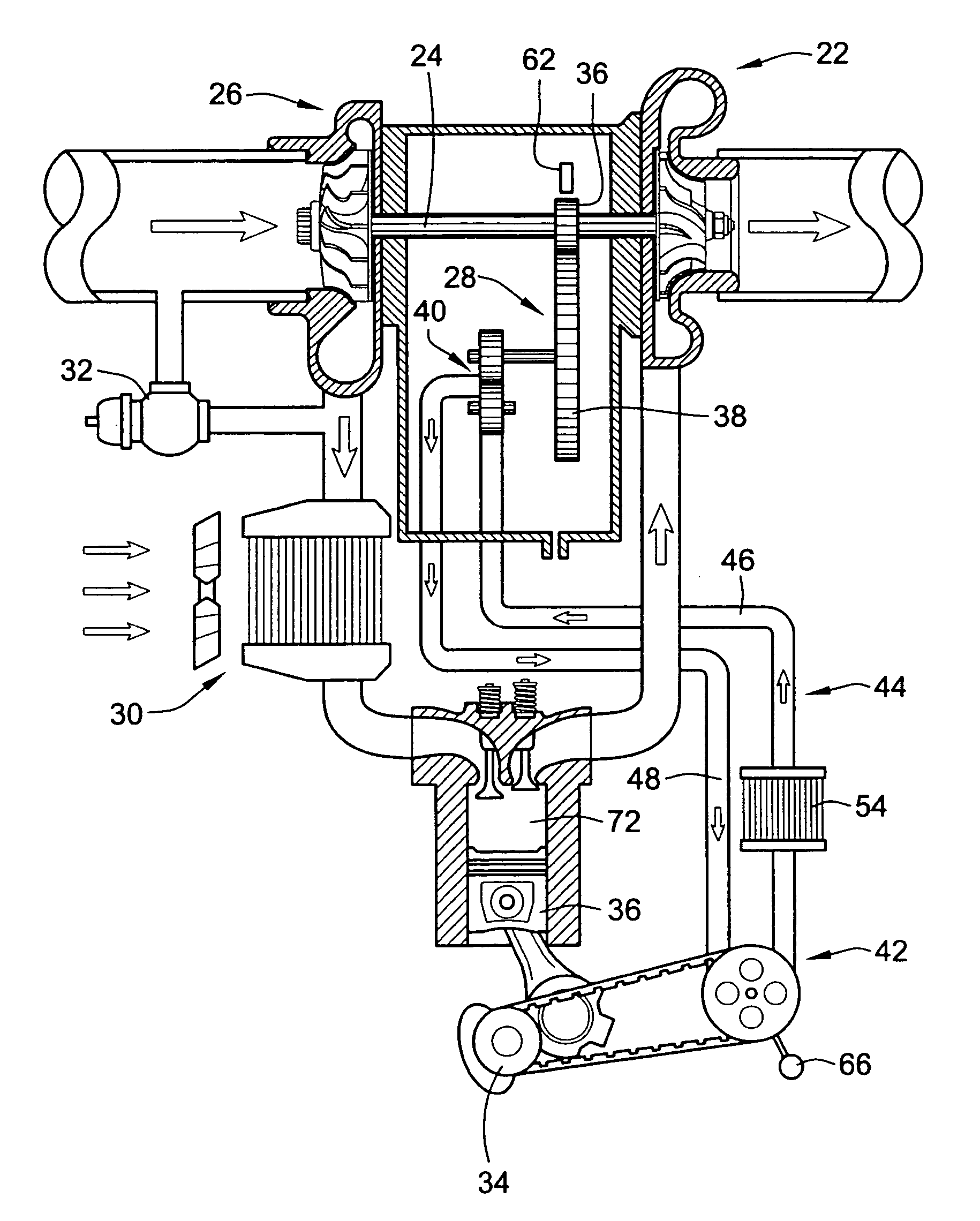
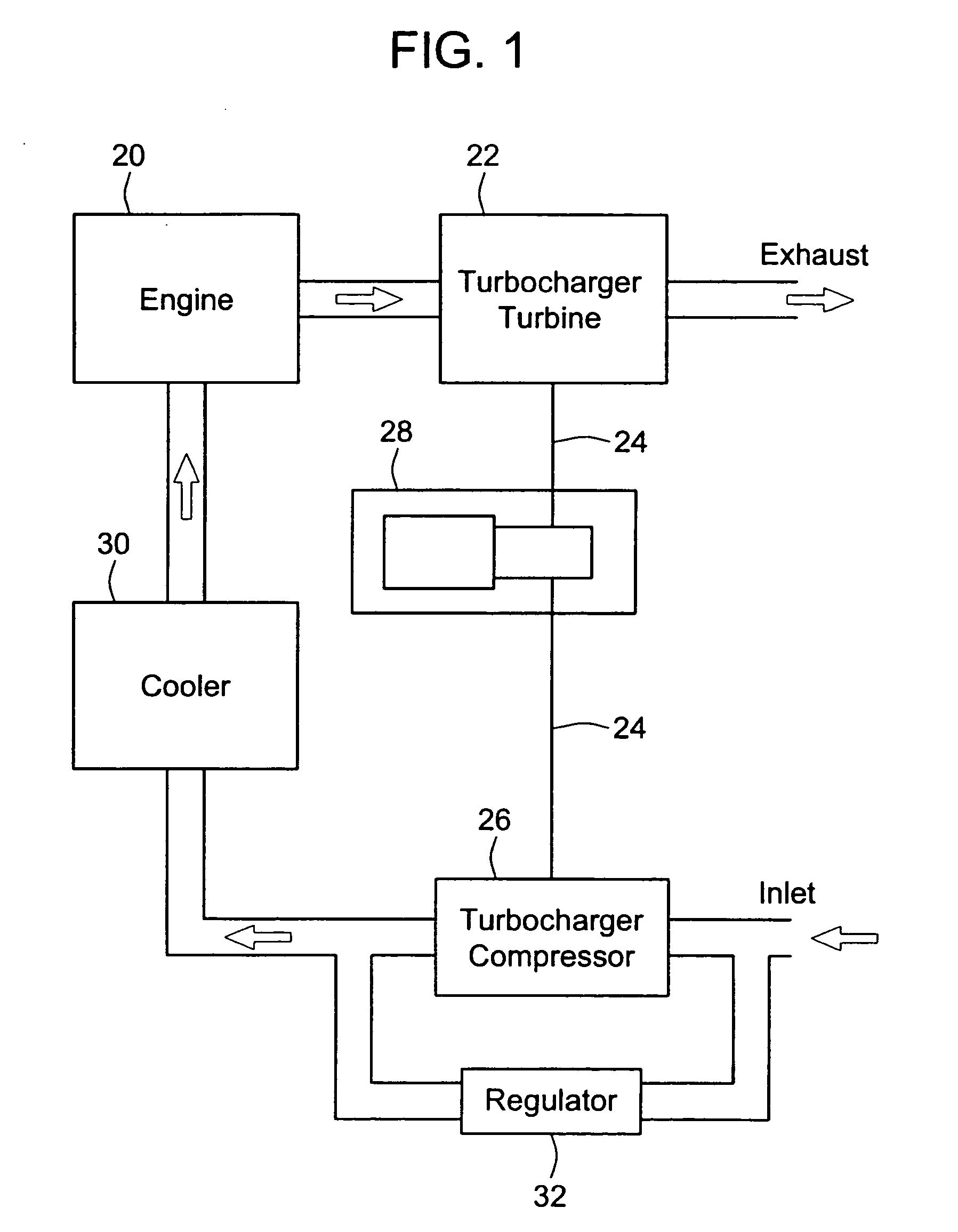
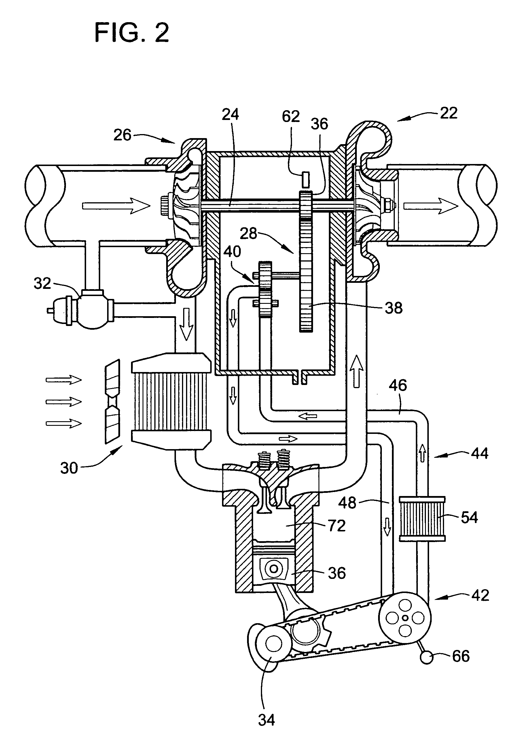
[0010] The invention combines the features of a supercharger and a turbocharger utilizing a hydraulic pump to drive the turbocharger up to a specific speed or intake manifold pressure and then hold back the turbocharger to keep it at the right speed for the engine condition. The invention merges the benefits of a supercharger, which is primarily good for high torque at low speed, and a turbocharger, which is usually only good for high horsepower at high speeds. Once the exhaust energy begins to provide more work than it takes to drive the intake compressor, the invention recovers that excess energy and puts it to work turning the crankshaft. As a result, the invention provides both the benefits of low speed with high torque and the added value of high speed with high horsepower all from one system. The power available from an engine system with a super-turbocharger is greater than that of a turbocharged engine due to the elimination of the wastegate, the larger overall size of the turbocharger, vanes that make the compressor and turbine more efficient, and the ability of the system to hold the turbocharger at an optimum speed.
[0013] During engine operating conditions in which the turbocharger is incapable of meeting the boost demands of the engine (such as low speed high torque operation), the variable ratio transmission is driven, which results in the acceleration of the mechanism being driven, thereby increasing the speed of the turbo-shaft. As a result, the turbocharger delivers more pressure and airflow to the intake manifold of the engine to meet the boost demands.

Problems solved by technology

During engine operating conditions in which the turbocharger is incapable of meeting the boost demands of the engine (such as low speed high torque operation), the variable ratio transmission is driven, which results in the acceleration of the mechanism being driven, thereby increasing the speed of the turbo-shaft.

Method used


Image

  • Super-turbocharger
  • Super-turbocharger
  • Super-turbocharger

Examples


Embodiment Construction

[0024] Turbocompounding is a way to harness excess exhaust energy that is not used by the turbine of the turbocharger. This is achieved by adding a second larger turbine attached to a transmission which is then attached to the output shaft of the engine. Turbocompounding can improve fuel economy by as much as 5%. This invention provide the best of both turbocompounding and supercharging all in one device. The invention provides a system that reduces turbocharger lag and harnesses excess exhaust energy from the turbocharger. The invention utilizes relatively inexpensive and commercially available components. The overall system cost of the system in accordance with the invention is believed to be equal to or less then that of a supercharger system and only slightly more expensive than a turbocharger system.

[0025] The invention combines the features of a supercharger and a turbocharger, utilizing a hydraulic pump to drive the turbocharger up to a specific speed or intake manifold pres...


PUM


Abstract

The invention combines the features of a supercharger, a turbocharger and turbo-compounding into one system, utilizing a hydraulic or mechanical continuously variable transmission to drive the turbocharger up to a specific speed or intake manifold pressure and then holding the ideal speed to keep it at the right boost pressure for the engine condition. The benefits of a supercharger, which is primarily good for high torque at low speed, and a turbocharger, which is usually only good for high horsepower at high speeds are merged. Once the exhaust energy begins to provide more work than it takes to drive the intake compressor, the invention recovers that excess energy and uses it to add torque to the crankshaft. As a result, the invention provides the benefits of low speed with high torque and the added value of high speed with higher horsepower or better fuel economy all from one system.

Description

CROSS-REFERENCE TO RELATED PATENT APPLICATIONS [0001] This patent application claims the benefit of U.S. Provisional Patent Application No. 60 / 601,844, filed Aug. 16, 2004.FIELD OF THE INVENTION [0002] This invention pertains to turbochargers, and more particularly to hydraulically driven turbochargers. BACKGROUND OF THE INVENTION [0003] Conventional turbochargers are driven by waste exhaust heat and gases, which are forced through an exhaust turbine housing onto a turbine wheel. The turbine wheel is connected by a common turbo-shaft to a compressor wheel. As the exhaust gases hit the turbine wheel, both wheels rotate simultaneously. Rotation of the compressor wheel draws air in through a compressor housing, which forces compressed air into the engine cylinder to achieve improved engine performance and fuel efficiency. Turbochargers for variable speed / load applications are typically sized for maximum efficiency at torque peak speed in order to develop sufficient boost to reach peak ...

Claims


Application Information

Patent Timeline
IPC IPC(8): F02B33/44
CPCF02B29/04F02B37/10F02B37/105F02B37/14F02B37/16Y10T74/19888F02B39/04F02B39/06F02B39/08Y02T10/144Y02T10/163F02B39/02F16H61/42Y02T10/12
Inventor DYNE, ED VANGENDRON, THOMAS A.
Owner VANDYNE SUPERTURBO
Learn More