Integrated circuit heat pipe heat spreader with through mounting holes

a heat spreader and integrated circuit technology, which is applied in the direction of cooling/ventilation/heating modification, semiconductor devices, lighting and heating apparatus, etc., can solve the problems of reducing the performance of the integrated circuit chip, reducing reliability, and large differences in the effectiveness of heat transfer from various parts of the heat sink, so as to achieve low cost, easy manufacturing, and simple structure

Inactive Publication Date: 2006-02-16
AAVID THERMALLOY LLV
View PDF38 Cites 8 Cited by
  • Summary
  • Abstract
  • Description
  • Claims
  • Application Information

AI Technical Summary

Benefits of technology

[0006] The present invention is an inexpensive heat pipe heat spreader for integrated circuit chips which is of simple, light weight construction. It is easily manufactured, requires little additional space, and provides additional surface area for cooling the integrated circuit and for attachment to heat transfer devices for moving the heat away from the integrated circuit chip to a location from which the heat can be more easily disposed of. Furthermore, the heat pipe heat spreader is constructed to assure precise flatness and to maximize heat transfer from the heat source and to the heat sink, and has holes through its body to facilitate mounting.
[0009] The spacers thus serve important purposes. They support the flat plates and prevent them from deflecting inward and distorting the plates to deform the flat surfaces which are required for good heat transfer. The spacers also serve as critical support for the portions of the capillary wick pillars which span the space between the plates provide a gravity independent characteristic to the heat spreader, and the spacers around which the wick pillars are located assure that the capillary wick is not subjected to destructive compression forces.

Problems solved by technology

This phenomenon can cause great differences in the effectiveness of heat transfer from various parts of a heat sink.
The effect of this unbalanced heat transfer is reduced performance of the integrated circuit chip and decreased reliability due to high operating temperatures.
However, these approaches increase weight, noise, system complexity, and expense.

Method used


Image

  • Integrated circuit heat pipe heat spreader with through mounting holes
  • Integrated circuit heat pipe heat spreader with through mounting holes
  • Integrated circuit heat pipe heat spreader with through mounting holes

Examples


Embodiment Construction

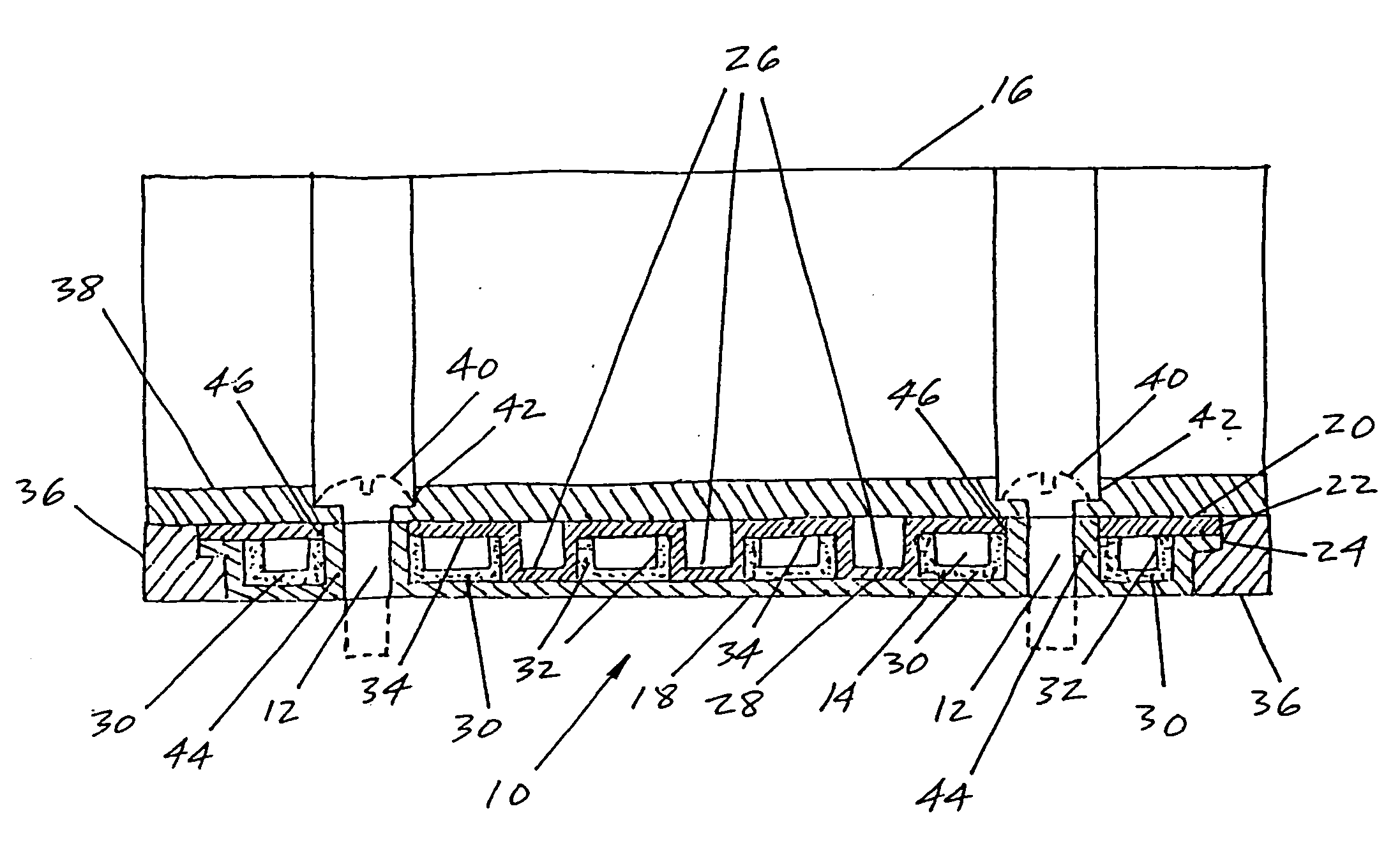
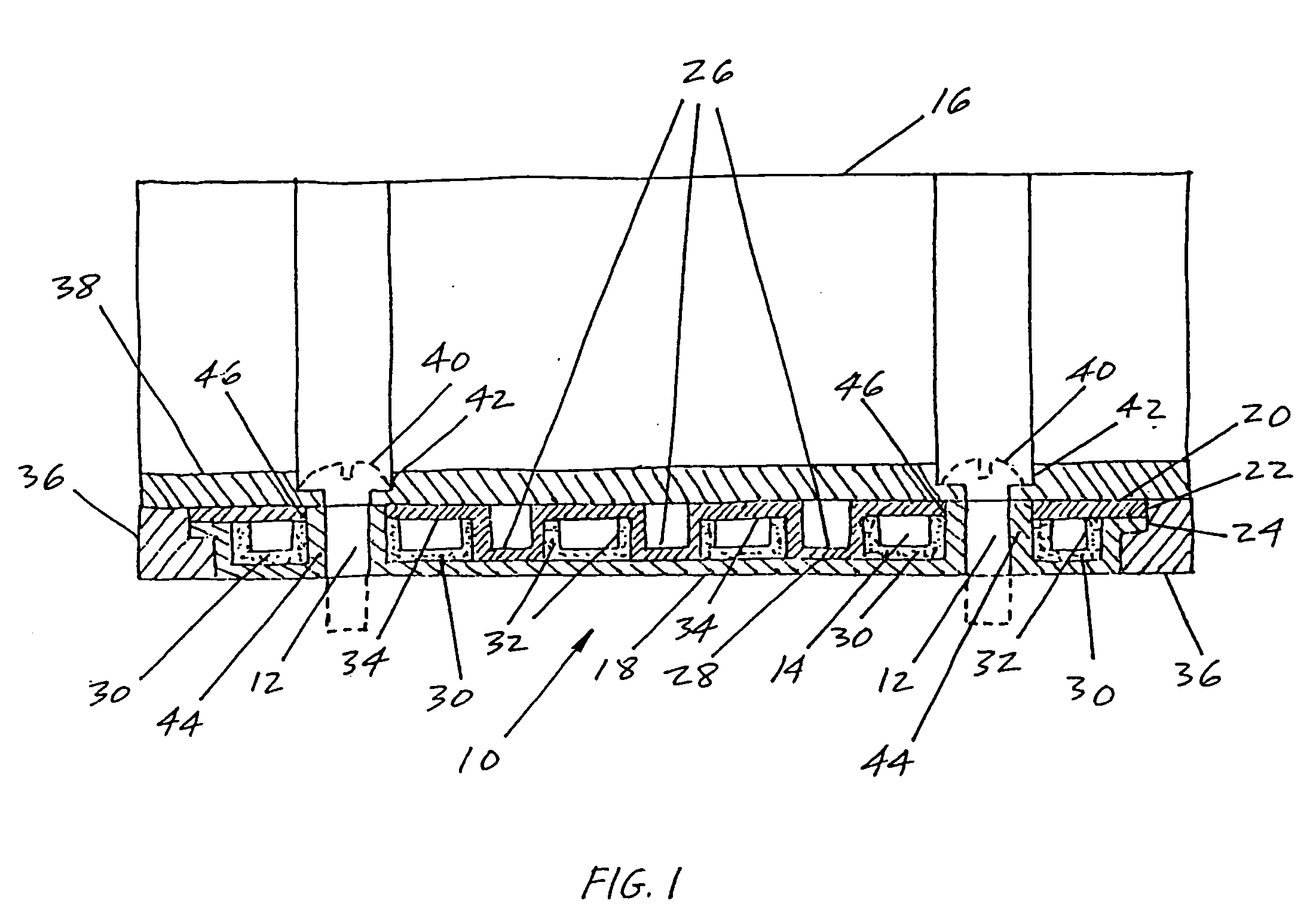
[0017]FIG. 1 is a cross section view of the preferred embodiment of a flat plate heat pipe 10 of the invention with through holes 12 through its vapor chamber 14 and in contact with finned heat sink 16.

[0018] Heat pipe 10 is constructed by forming a boundary structure by sealing together two formed plates, contact plate 18 and cover plate 20. Contact plate 18 and cover plate 20 are sealed together at their peripheral lips 22 and 24 by conventional means, such as soldering or brazing, to form heat pipe 10. Heat pipe 10 is then evacuated to remove all non-condensible gases and a suitable quantity of heat transfer fluid is placed within it. This is the conventional method of constructing a heat pipe, and is well understood in the art of heat pipes.

[0019] The interior of heat pipe 10 is, however, constructed unconventionally. While contact plate 18 is essentially flat with the exception of peripheral lip 24, cover plate 20 includes multiple depressions 26. Depressions 26 are formed an...


PUM


Abstract

The apparatus is a heat pipe with superior heat transfer between the heat pipe and the heat source and heat sink. The heat pipe is held tightly against the heat source by mounting holes which penetrate the structure of the heat pipe but are sealed off from the vapor chamber because they each are located within a sealed structure such as a pillar or the solid layers of the casing surrounding the vapor chamber. Another feature of the heat pipe is the use of more highly heat conductive material for only that part of the wick in the region which contacts the heat source, so that there is superior heat conductivity in that region.

Description

CROSS-REFERENCE TO RELATED APPLICATIONS [0001] This application is a Divisional application of copending U.S. Ser. No. 10 / 739,709, filed on Dec. 13, 2003, which is itself a Continuation application of copending U.S. application Ser. No. 09 / 852,322, filed on May 9, 2001, which is itself a continuation application of U.S. application Ser. No. 09 / 310,397, filed on May 12, 1999, and now issued as U.S. Pat. No. 6,302,192.BACKGROUND OF THE INVENTION [0002] This invention relates generally to active solid state devices, and more specifically to a heat pipe for cooling an integrated circuit chip, with the heat pipe designed to be held in direct contact with the integrated circuit. [0003] As integrated circuit chips decrease in size and increase in power, the required heat sinks and heat spreaders have grown to be larger than the chips. Heat sinks are most effective when there is a uniform heat flux applied over the entire heat input surface. When a heat sink with a large heat input surface ...

Claims


Application Information

Patent Timeline
Patent Type & Authority Applications(United States)
IPC IPC(8): H05K7/20F28D15/00F28D15/02F28D15/04H01L23/427
CPCF28D15/0233F28D15/046H01L23/427H01L2924/0002H01L2924/00
Inventor DUSSINGER, PETER M.MYERS, THOMAS L.
Owner AAVID THERMALLOY LLV
Why Eureka
Try Eureka