Lead terminal and power supply device

a technology of lead terminal and power supply device, which is applied in the direction of secondary cell servicing/maintenance, cell components, and association of printed circuit non-printed electric components, etc., can solve the problems of lowering energy utilization efficiency, and achieve the effects of increasing the electrical resistance of the welding portion, high welding strength, and reducing the number of fuses

Inactive Publication Date: 2006-02-16
SONY CORP
View PDF0 Cites 81 Cited by
  • Summary
  • Abstract
  • Description
  • Claims
  • Application Information

AI Technical Summary

Benefits of technology

[0025] In the power supply apparatus according to the present invention, current for resistance-welding flows to much degree in a thickness direction of the lead terminal so that electric resistance of the welding portion is increased. As a result, calorific value produced at the contact portion between the external terminal of the battery and the welding portion of the lead terminal also becomes large. Thus, it is possible to suitably resistance-weld the welding portion of the lead terminal to the external terminal of the battery with high welding strength.
[0026] In this power supply apparatus, since the conductive portion at the lead terminal is thicker than the welding portion, it is possible to suppress electric resistance between the welding portion and the connecting portion, which is produced when electricity for charging / discharging the battery is caused to flow in the lead terminal, i.e., electric resistance of the conductive portion. Accordingly, electric resistance of the conductive portion at the lead terminal is suppressed, thereby making it possible to suppress heat of the lead terminal by electric resistance when electricity is caused to flow in the lead terminal.
[0027] In addition, in the power supply apparatus according to the present invention, electric resistance of the lead terminal is suppressed so that voltage drop and power loss at the time of charge / discharge operation can be reduced. Thus, the charge / discharge efficiency is permitted to be satisfactory.

Problems solved by technology

As a result, power loss takes place, leading to lowering of energy utilization efficiency.

Method used


Image

  • Lead terminal and power supply device
  • Lead terminal and power supply device
  • Lead terminal and power supply device

Examples


Embodiment Construction

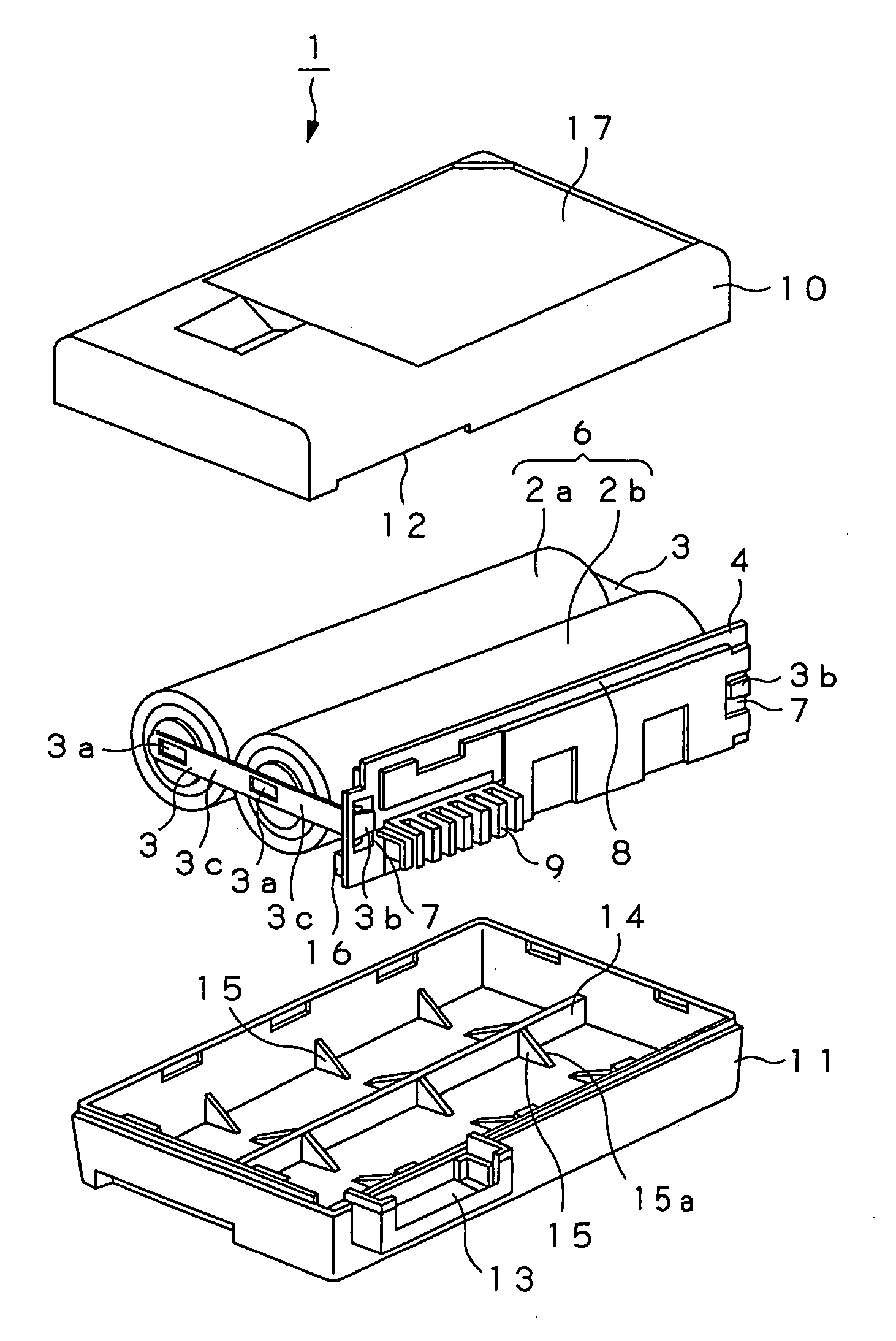
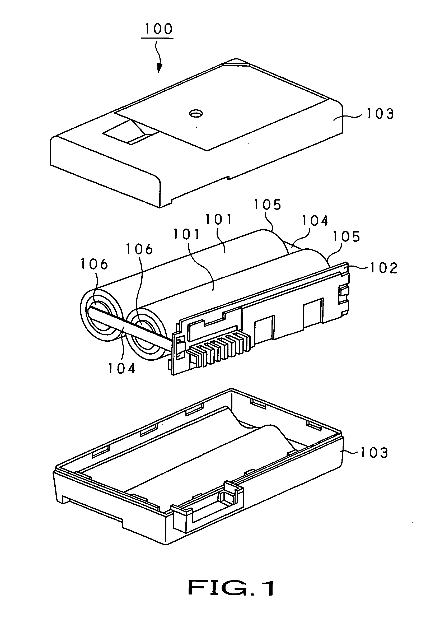
[0052] A lead terminal and a power supply apparatus using such a lead terminal according to the present invention will now be explained with reference to a battery pack 1 shown in FIGS. 4 and 5. The battery pack 1 is loaded with respect to a loading portion provided at electronic equipment, etc., e.g., camera integrated type VTR, etc. to have ability to stably deliver power of a predetermined voltage to the electronic equipment, etc.

[0053] Further, the battery pack 1 includes a pair of substantially cylindrical batteries 2a, 2b which serve as power generating element, lead terminals 3 connected to external terminals of the pair of batteries 2a, 2b, and a circuit wiring board 4 electrically connected to the pair of batteries 2a, 2b through the lead terminals 3 to thereby perform control of charge / discharge operation with respect to the pair of batteries 2a, 2b, wherein the pair of batteries 2a, 2b, the lead terminals 3 and the circuit wiring board 4 are accommodated within a substan...


PUM

PropertyMeasurementUnit
currentaaaaaaaaaa
thicknessaaaaaaaaaa
thicknessaaaaaaaaaa

Abstract

The present invention is directed to a power supply apparatus in which a battery and a circuit wiring board or boards are electrically connected by using lead terminals. The lead terminal (3) is adapted so that thickness of a welding portion (3a) is caused to be thinner than the thickness of a conductive portion (3b). Thus, current for welding flows to much degree in a thickness direction so that electric resistance of the welding portion becomes large, and heat based on the electric resistance also becomes large. From this fact, welding nugget (63) can be enlarged. As the result of the fact that large welding nugget is formed, the lead terminals are welded to terminal portions (37a) of the battery (2) with high reliability.

Description

TECHNICAL FIELD [0001] The present invention relates to a lead terminal connected to a connected body with sufficient strength, and a power supply apparatus adapted for electrically connecting a battery and a circuit wiring board or boards by using such a lead terminal or terminals. [0002] This Application claims priority of Japanese Patent Application No. 2003-015167, filed on Jan. 23, 2003, the entirety of which is incorporated by reference herein. BACKGROUND ART [0003] Hitherto, as a power supply of an electronic equipment such as note type personal computer, mobile telephone, camera integrated type VTR (Video Tape Recorder) and / or PDA (Personal Digital Assistants), etc., a light secondary battery having high energy density is required. As the secondary battery having high energy density of this kind, there is lithium ion secondary battery having energy density larger than that of aqueous electrolyte battery, e.g., lead battery, nickel-cadmium battery and / or nickel-hydrogen batte...

Claims


Application Information

Patent Timeline
Patent Type & Authority Applications(United States)
IPC IPC(8): H05K1/09H05K1/18B23K11/00H01M10/42H01M50/51H01M50/516H01M50/522H01M50/524H01M50/526H01R4/02H01R11/28
CPCB23K11/004B23K2201/36H01M2/105H01R11/281H01M10/0525H01M10/425H01R4/029H01M2/204B23K2101/36Y02E60/10H01M50/213H01M50/522H01M50/526H01M50/516H01M50/51H01M50/524H01R4/02
Inventor SATO, BUNYA
Owner SONY CORP
Why Eureka
Try Eureka