Infrared heating element and a substrate type vacuum chamber, particularly for vacuum coating facilities

Inactive Publication Date: 2006-02-16
APPLIED MATERIALS GMBH & CO KG
View PDF13 Cites 0 Cited by
  • Summary
  • Abstract
  • Description
  • Claims
  • Application Information

AI Technical Summary

Benefits of technology

[0009] The object of the present invention is to make available an infrared heating element which transfers heat very effectively as a result of thermal radiation, particularly in a vacuum. A further object of the present invention is to provide a substrate heater, particularly for vacuum coating facilities, which permits a substrate to be heated very effectively by means of thermal radiation. In this context, the term “effective” means on the one hand that the ratio of the total energy emitted to the thermal radiation energy used for heating is optimized, in other words, losses are reduced. On the other hand, however, the aim is also to minimize the temperature of the heating element compared to the temperature reached by the object to be heated.

Problems solved by technology

It is hard to equip this kind of carrier with a heating plate, such as a BN resistance substrate heater.
Furthermore, it requires a great deal of time and effort to produce contact surfaces for a heating plate which has such a smooth and level surface as to ensure the transfer of heat to the substrate over the entire surface area.
If only localized points on the substrate lie on the heating surface, a sensitive substrate may be destroyed by thermal stresses because the vacuum does not contain any contact medium that produces the heat transfer, such as atmospheric air.
In this case, too, it is not possible to heat the substrate by way of thermal conduction, because the substrate is exposed.
The problem with such thermal radiators is that apart from infrared radiation, radiation in the visible and ultraviolet ranges is always emitted.
As a result, the transferred heating capacity is limited compared to that which is radiated in total.

Method used


Image

  • Infrared heating element and a substrate type vacuum chamber, particularly for vacuum coating facilities
  • Infrared heating element and a substrate type vacuum chamber, particularly for vacuum coating facilities

Examples


Embodiment Construction

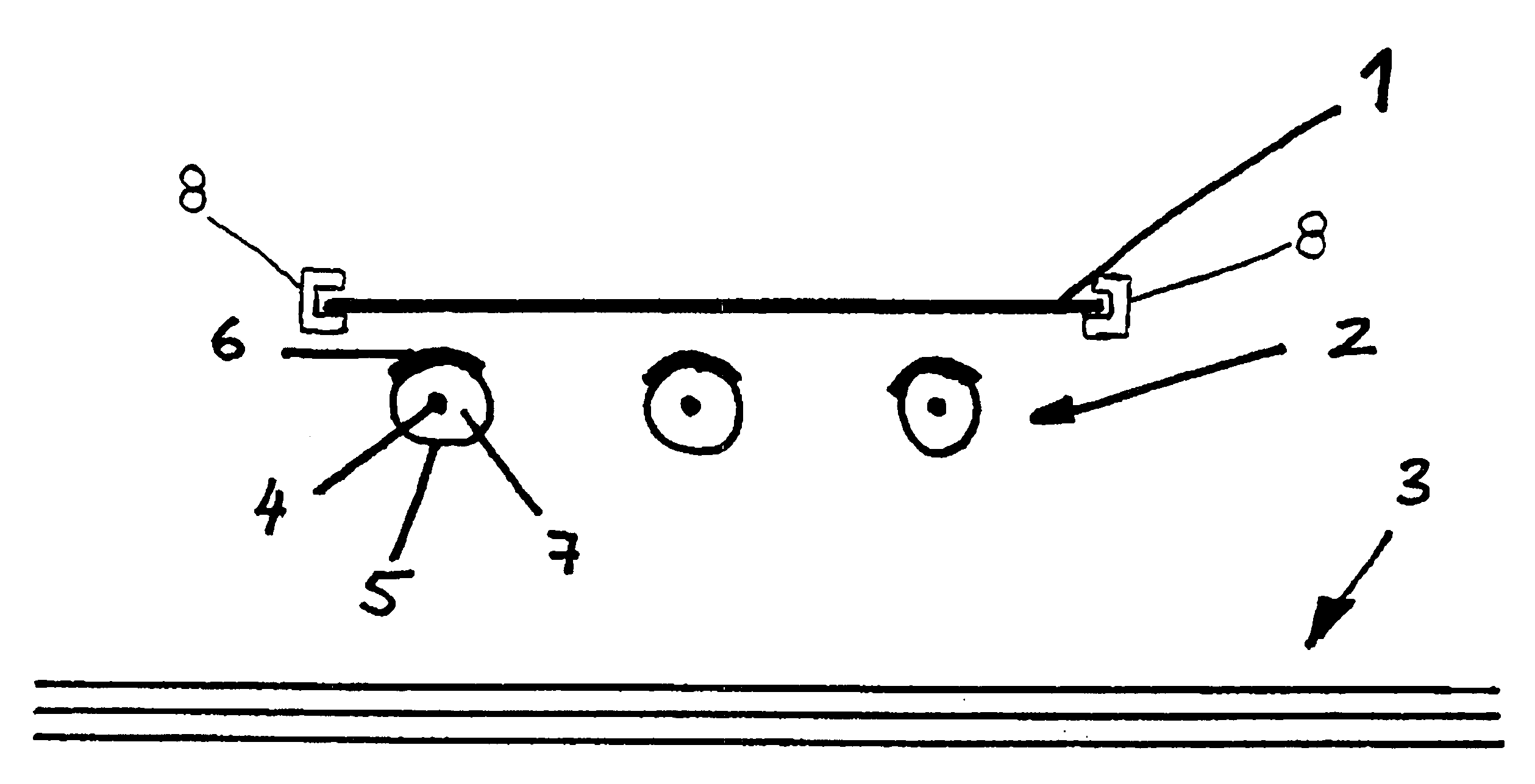
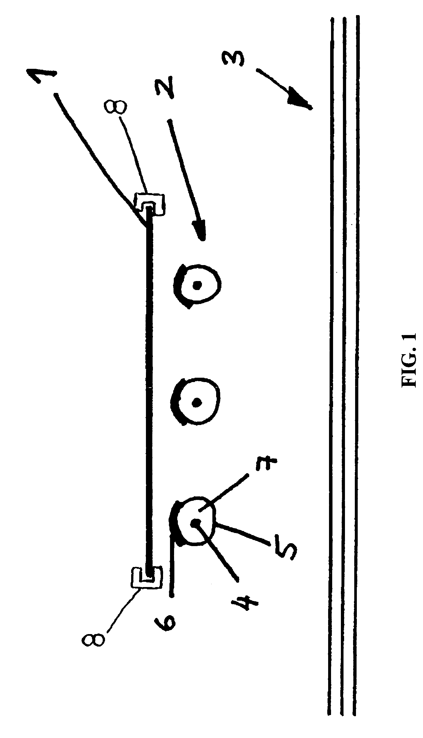
[0012] The infrared heating element according to the invention comprises a heating source that is surrounded by a protective means designed as a tubular metal jacket. The tubular jacket is coated at least to an extent with an infrared-emitting layer. The heating source sheath in the form of a tubular metal jacket not only protects the heating source, but also brings about an even distribution of heat as a result of thermal conduction within the tubular jacket. The fact that the tubular jacket is coated at least in part with an infrared-emitting layer increases the effectiveness of thermal radiation and enables the jacket temperature to drop while retaining the radiated thermal energy.

[0013] It is beneficial for the metal to have an emittance of between 0.1 and 0.4 and for the infrared-emitting layer to have an emittance of more than 0.7, preferably of more than 0.8 and particularly of more than 0.9. Such an infrared-emitting layer approximates a black body very closely in terms of ...


PUM


Abstract

The present invention relates to an infrared heating element and a substrate heater type vacuum chamber, particularly for vacuum coating facilities. The infrared heating element comprises a heating source which is surrounded by a protective means designed as a tubular metal jacket. The tubular metal jacket is provided at least to an extent with an infrared-emitting layer. The vacuum chamber comprises a substrate and at least one heating element that is designed as an infrared heating element, the substrate and infrared heating element being thermally decoupled in such a way that only thermal radiation contributes toward heating.

Description

BACKGROUND AND TECHNICAL FIELD OF THE INVENTION [0001] The invention relates to an infrared heating element and a substrate heater type vacuum chamber, particularly for vacuum coating facilities, in accordance with the preamble of claim 1 and claim 10. [0002] Heat can be transferred spatially as a result of thermal conduction, thermal radiation and thermal convection. Whereas thermal conduction occurs by way of molecular collisions and hence requires a temperature gradient in matter, thermal convection depends on macroscopic movements in liquids or gases, the heat content of which is conveyed to other points. Thermal radiation is electromagnetic in nature. [0003] The substrate cannot be heated directly by thermal conduction as regards certain processes. For example, the substrate can be attached to a movable substrate holder (carrier) which moves the substrate through various process chambers. It is hard to equip this kind of carrier with a heating plate, such as a BN resistance sub...

Claims


Application Information

Patent Timeline
IPC IPC(8): H05B3/10
CPCH05B2203/032H05B3/0033
Inventor HAAS, DIETER
Owner APPLIED MATERIALS GMBH & CO KG
Why Eureka
Try Eureka