Displaying optical system and image projection apparatus

a technology of optical system and image projection apparatus, which is applied in the field of display optical system, can solve the problems of affecting the sharpness of the image displayed by the image projection apparatus, affecting the image quality of the image, so as to reduce the noise of speckles and the effect of loss of light amoun

Inactive Publication Date: 2006-02-16
CANON KK
View PDF8 Cites 212 Cited by
  • Summary
  • Abstract
  • Description
  • Claims
  • Application Information

AI Technical Summary

Benefits of technology

[0014] One object of the present invention is to provide a compact displaying optical system capable of reducing the speckle noise and a loss of light amount.

Problems solved by technology

On the other hand, since the laser beam has high coherence, an interference pattern, which is called a “speckle noise” and caused by the roughness of the screen, appears when the laser beam is projected on the screen.
The interference pattern causes degradation of sharpness of the image displayed by the image projection apparatus.
As a result, it becomes difficult to downsize the optical system.
Moreover, in the method disclosed in U.S. Pat. No. 6,323,984, the optical system becomes complex because the phase modulator is arranged at the position conjugated with the light modulator.

Method used


Image

  • Displaying optical system and image projection apparatus
  • Displaying optical system and image projection apparatus
  • Displaying optical system and image projection apparatus

Examples


embodiment 1

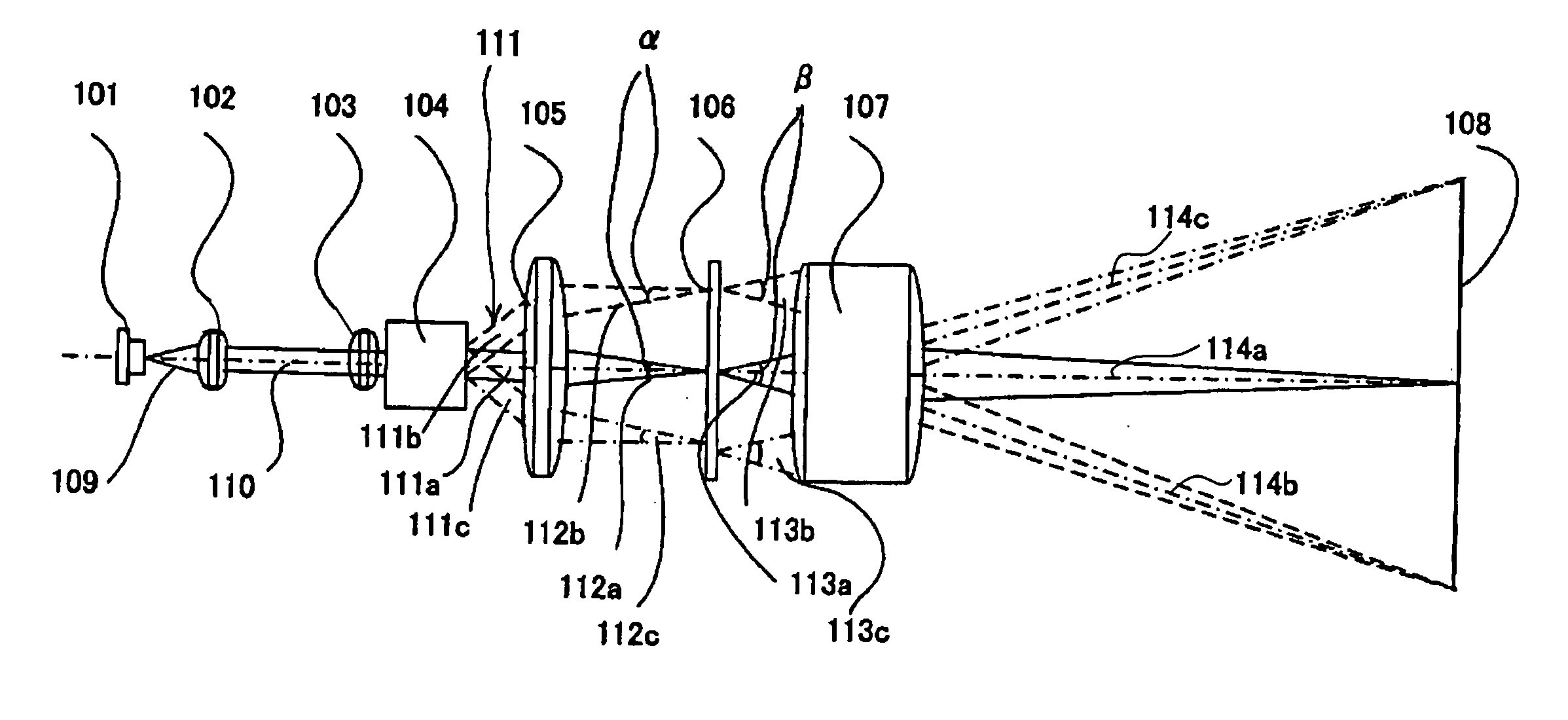
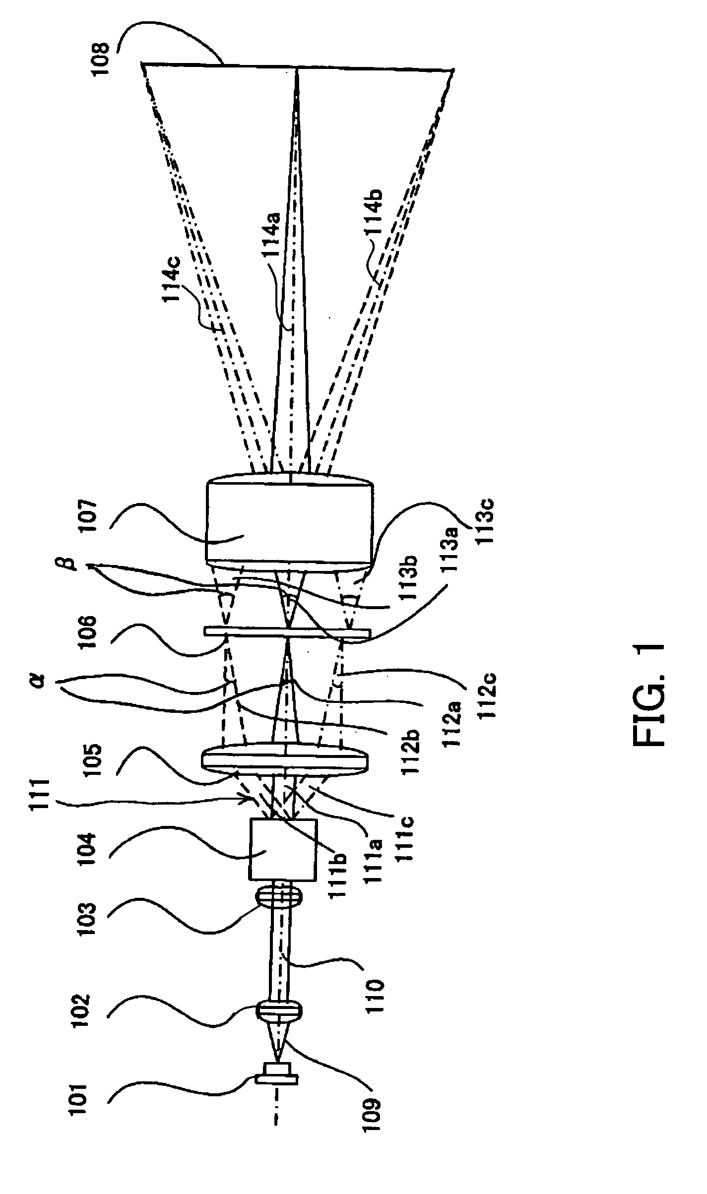
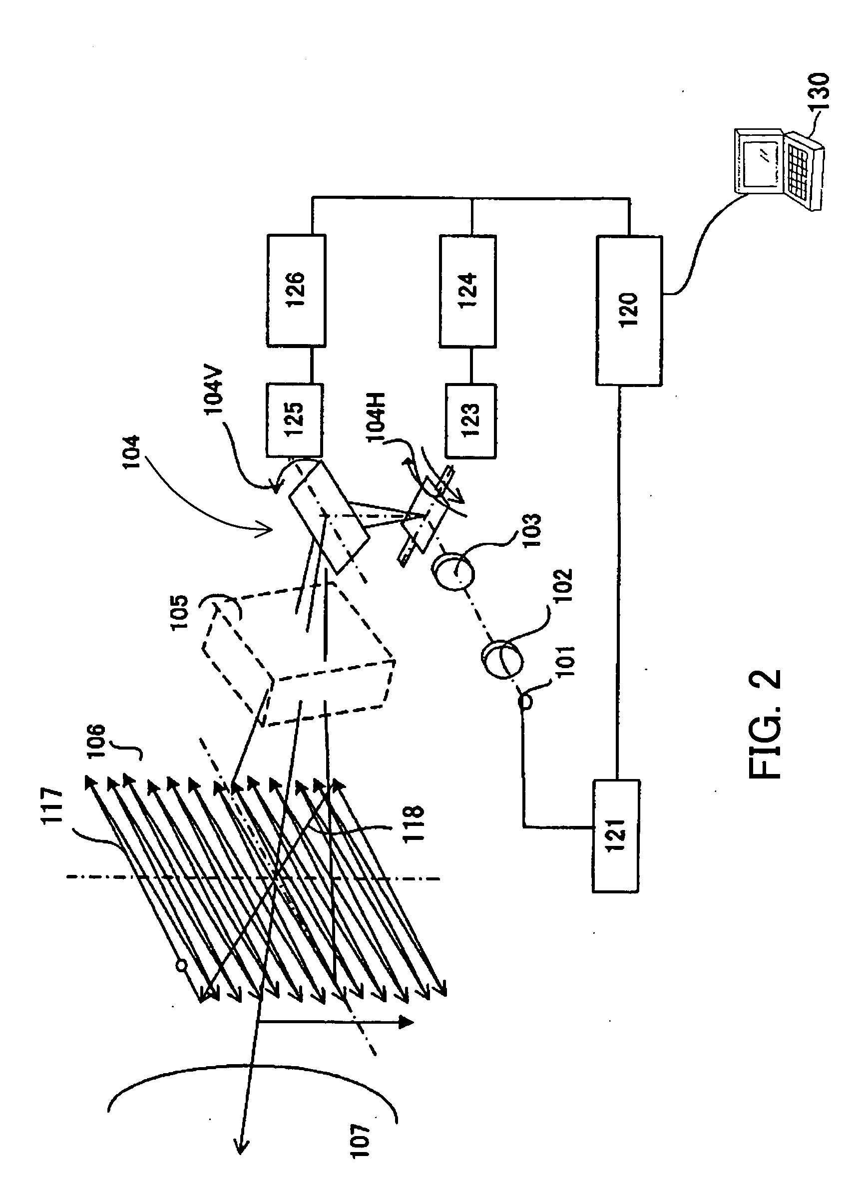
[0031]FIGS. 1 and 2 show the schematic structure of a laser scanning displaying optical system for an image projection apparatus that is Embodiment 1 of the present invention. FIG. 1 is a development view of the optical system shown in FIG. 2, the optical system being extended linearly in its optical axis direction in FIG. 1.

[0032] In FIGS. 1 and 2, reference numeral 101 denotes a laser source which is a light source emitting coherent light. The luminous flux 109 emitted from the laser source 101 is converted into a substantially parallel beam (hereinafter, it is referred to as a laser beam) 110 by a collimator optical system 102 as shown in FIG. 1.

[0033] A light-source modulator 121 is connected to the laser source 101. A projection controlling circuit 120 is connected to the light-source modulator 121. An image-signal supplying apparatus 130 such as a personal computer, DVD player, videocassette recorder, or television tuner is connected to the projection controlling circuit 120...

embodiment 2

[0058]FIG. 6 shows the schematic structure of a laser scanning displaying optical system for an image projection apparatus that is Embodiment 2 of the present invention. This embodiment uses a reflective divergence-angle conversion element 206 though Embodiment 1 uses a transmissive divergence-angle conversion element 106.

[0059] In FIG. 6, reference numeral 201 denotes a laser source which is a light source emitting coherent light. The luminous flux 209 emitted from the laser source 201 is converted into a substantially parallel laser beam 210 by a collimator optical system 202. The laser beam 210 emerged from the collimator optical system 202 enters a condensing optical system 203, and then impinges on a two-dimensional scanning device 204. The two-dimensional scanning device 204 scans the laser beam 210 at a high speed in predetermined two-dimensional directions. FIG. 6 exemplifies the laser beams 211a, 211b and 211c, which are three of the laser beams scanned by the two-dimensio...

embodiment 3

[0077]FIG. 10 shows the schematic structure of a laser scanning displaying optical system for an image projection apparatus that is Embodiment 3 of the present invention. This embodiment uses a reflective divergence-angle conversion element as Embodiment 2. However, the configuration of the scanning optical system is different from that of Embodiment 2.

[0078] In FIG. 10, reference numeral 301 denotes a laser source which is a light source emitting coherent light. The luminous flux 309 emitted from the laser source 301 is converted into a substantially parallel laser beam 310 by a collimator optical system 302. The laser beam 310 emerged from the collimator optical system 302 enters a condensing optical system 303, and then impinges on a two-dimensional scanning device 304. The two-dimensional scanning device 304 scans the laser beam 310 at a high speed in predetermined two-dimensional directions. FIG. 10 exemplifies the laser beams 311a, 311b and 311c, which are three of the laser ...


PUM


Abstract

A displaying optical system is disclosed, which is capable of reducing a speckle noise. The displaying optical system comprises a light source emitting coherent light, a scanning device scanning the light, a first optical system causing the light from the scanning device to form an intermediate image, a second optical system causing the light from the intermediate image to form an image on a real display surface, and an optical element arranged between the first and second optical systems. The optical element widens the divergence angle of the light emerged from the optical element toward the second optical system more than the incident angle of the light on the optical element from the first optical system.

Description

FIELD OF THE INVENTION [0001] The present invention relates to a displaying optical system which projects images using coherent light (light with coherence) such as a laser beam. BACKGROUND OF THE INVENTION [0002] Various image projection apparatuses which project images using a laser beam have been proposed. Since the laser beam has a very narrow spectral width, it is possible to provide a display having a wide range of color reproduction by using three colored lasers of red, blue, and green. [0003] Since laser light has a strong directivity and its energy density can be heightened, it is possible to perform beam-formation of the light from the laser source and scan the laser beam by a compact scanning device. Therefore, there is a possibility of realizing a compact image projection apparatus. For example, Japanese Patent Laid-Open No. H07-151995 has disclosed a laser scanning display in which a scanning device scans a laser beam to display images on a screen as an image projection...

Claims


Application Information

Patent Timeline
Patent Type & Authority Applications(United States)
IPC IPC(8): H01L27/00
CPCH04N9/3129G02B27/48
Inventor KOBAYASHI, SHUICHIISHIHARA, KEIICHIROSAKAGUCHI, RYUICHI
Owner CANON KK
Why Eureka
Try Eureka