

Switch driver with slew rate control
a technology of slew rate control and switch driver, which is applied in the direction of voltage/current interference elimination, pulse technique, reliability increasing modifications, etc., can solve the problems of large transient current, large transient current damage to circuitry transistors, and difficult proposition of providing power to circuitry in an integrated circuit (via turning on an internal voltage rail). increase the rise time of a current flow, reduce the magnitude and abruptness of the current, effect of increasing the rise tim
- Summary
- Abstract
- Description
- Claims
- Application Information
AI Technical Summary
Benefits of technology
Problems solved by technology
Method used
Image

Examples
Embodiment Construction
[0024] The making and using of the presently preferred embodiments are discussed in detail below. It should be appreciated, however, that the present invention provides many applicable inventive concepts that can be embodied in a wide variety of specific contexts. The specific embodiments discussed are merely illustrative of specific ways to make and use the invention, and do not limit the scope of the invention.
[0025] The present invention will be described with respect to preferred embodiments in a specific context, namely a header switch for providing power to logic circuitry in an integrated circuit. The invention may also be applied, however, to other power supply applications, wherein there is an interest in reducing power-on transient currents and there is sensitivity to large transient currents.
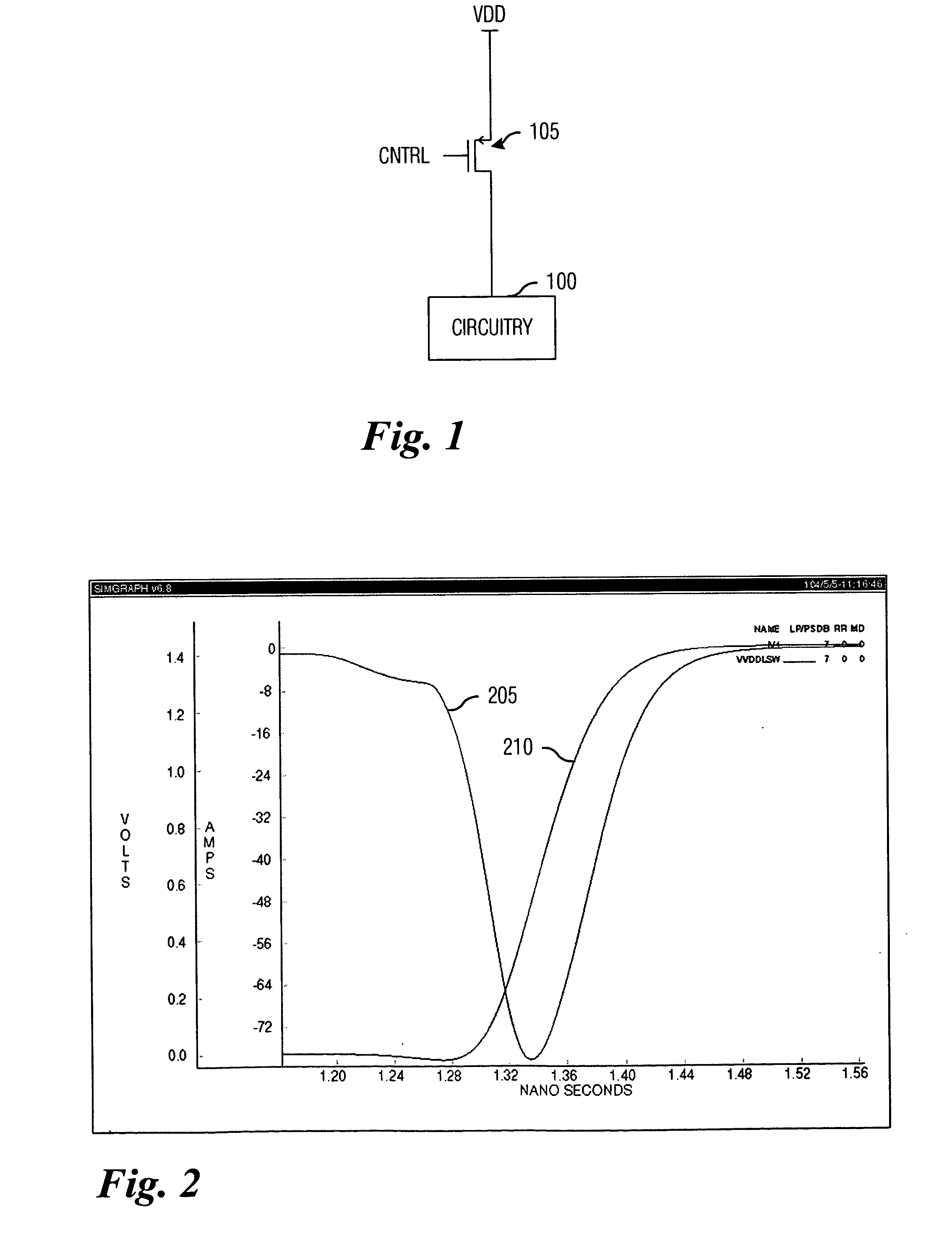
[0026] With reference now to FIG. 1, there is shown a diagram illustrating an arrangement for providing power to circuitry 100 in an integrated circuit through the use of a transist...
PUM
 Abstract
Description
Claims
Application Information