Capacitor and method of connecting the same

a technology of capacitors and connectors, applied in the field of capacitors, can solve the problems of shortening the life of capacitors and incurred circuit malfunctions, and achieve the effects of promoting the deterioration of rubber-like elastic members, enhancing the sealing effect, and ensuring the integrity of the capacitor

Inactive Publication Date: 2006-02-16
PANASONIC CORP
View PDF4 Cites 26 Cited by
  • Summary
  • Abstract
  • Description
  • Claims
  • Application Information

AI Technical Summary

Benefits of technology

[0053] With this construction, the electrically-insulating layer is provided at the opening portion of the metallic casing and its vicinity. For example, the metallic casing is made of an aluminum material, and the open end portion and its vicinity are immersed in a solution of 14±1 W/V % sulfuric acid while a liquid temperature is maintained at 21±2° C., and a voltage of 15±3V is applied for about 40 minutes at a current density of 110±40 A/m2, with the metallic casing serving as an anode. By doing so, the anodized aluminum layer can be formed. However, this anodized aluminum layer has defective portions, and in order to seal the defective portions, that portion, having the anodized aluminum layer formed thereon, is immersed, for example, in an aqueous solution, which contains 5.5±0.5 g/L of nickel acetate and 1.5±0.5 g/L of additive, and is maintained at a temperature of not lower than 90 degrees, for 10 to 20 minutes. By doing so, the defective portions are sealed, and as a result the anodized aluminum layer, that is, the electrically-insulating layer, having no defective portion, can be provided at the open end portion of the metallic casing and its vicinity, and therefore there is obtained an operational effect that the reliability of the sealing can be enhanced even during a long-term use.
[0054] The invention of claim 29, depending from claim 1 or claim 11, is directed to a construction in which the open end portion of the metallic casing is

Problems solved by technology

When the drive electrolyte thus leaks to the exterior, this has invited not only a problem that the lifetime of the capacitor is shortened but also a problem that when the drive electrolyte deposits in a bridging

Method used


Image

  • Capacitor and method of connecting the same
  • Capacitor and method of connecting the same
  • Capacitor and method of connecting the same

Examples


first embodiment

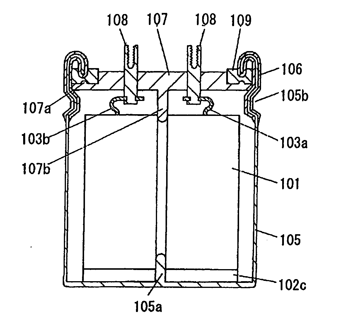
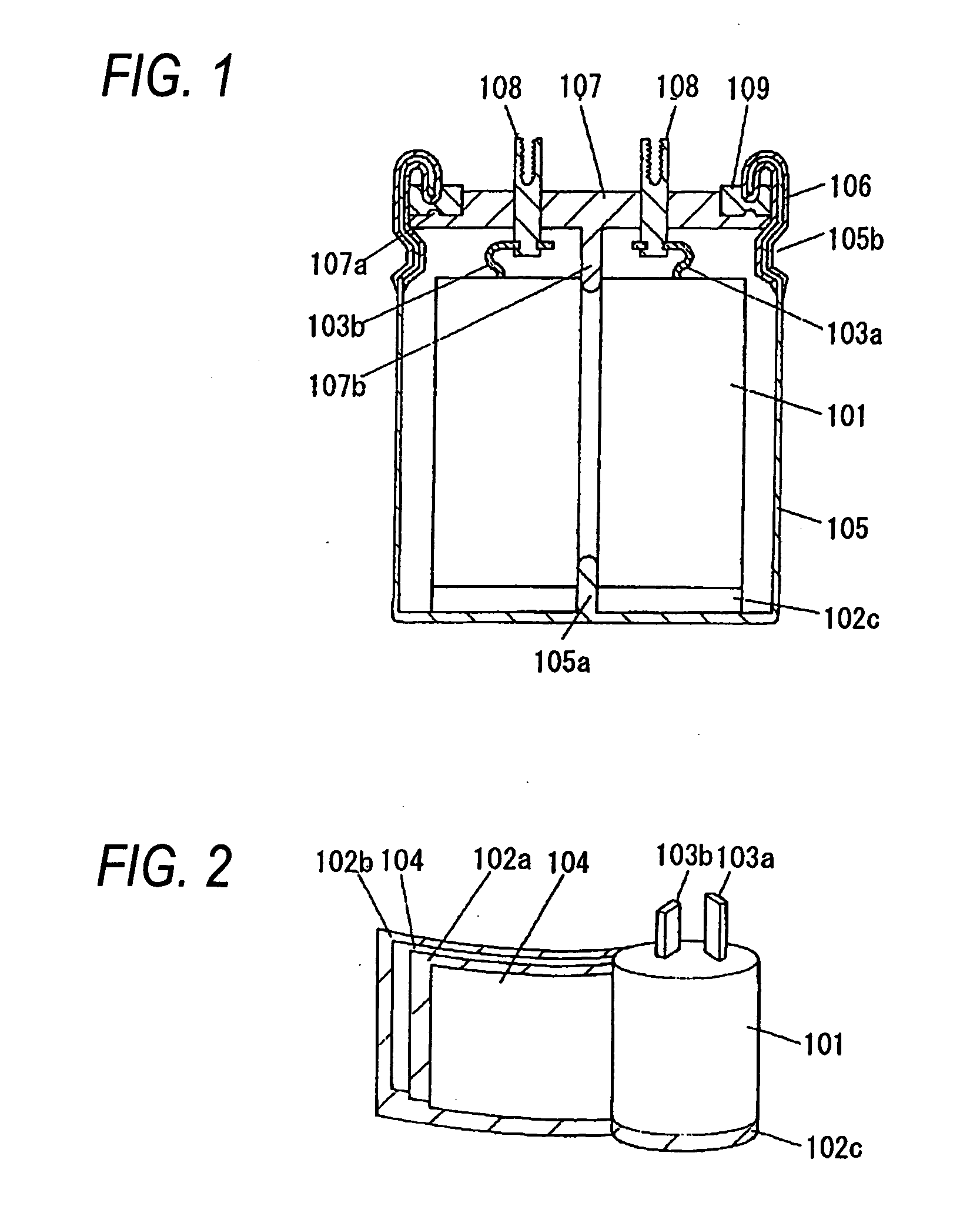
[0076]FIG. 1 is a cross-sectional view showing the construction of a first embodiment of a capacity of the invention, and FIG. 2 is a developed, perspective view of a capacitor element employed in this capacitor. In FIG. 1, reference numeral 101 denotes the capacitor element, and as shown in FIG. 2, this capacitor element 101 is obtained by connecting lead-out leads 103a and 103b respectively to a pair of electrodes 102a and 102b and then by winding these electrodes into a roll with separators 4 interposed therebetween in such a manner that one end surface 102c of one electrode 102b projects. Polarizable electrodes, each composed of a mixture comprising at least activated carbon, a binding agent and an electrically-conducting agent, are formed at the pair of electrodes 102a and 102b, respectively.

[0077] Reference numeral 105 denotes a tubular metallic casing with a closed bottom, and reference numeral 106 denotes an electrically-insulating layer formed on the metallic casing to cov...

second embodiment

[0089]FIG. 5 is a cross-sectional view showing the construction of a second embodiment of a capacity of the invention, and FIGS. 6(a) and 6(b) are a developed, perspective view and a perspective view respectively of a capacitor element employed in this capacitor. In FIG. 5, reference numeral 111 denotes the capacitor element, and in this capacitor element 111, polarizable electrode layers 113a and 113b, each composed of a mixture comprising at least activated carbon, a binding agent and an electrically-conducting agent, are formed in such a manner that electrode end surfaces 112a and 112b of a pair of electrodes 112 project in opposite directions, respectively as shown in FIG. 6(a). The pair of electrodes 112 are wound into a roll, with separators 114 interposed therebetween, and by doing so, the capacitor element 111 as shown in FIG. 6(b) can be obtained.

[0090] Reference numerals 115a and 115b denote lead-out leads connected respectively to upper and lower flat surface portions of...

third embodiment

[0097]FIG. 7 is a cross-sectional view showing the construction of a third embodiment of a capacitor of the invention, and this embodiment is similar in construction to the second embodiment except that an electrically-insulating plate 121 is provided between the lead-out leads 115a and 115b of the second embodiment.

[0098] With this construction, the short-circuiting between the lead-out leads 115a and 115b due to mechanical vibration is prevented, so that the capacitor of excellent insulating properties can be obtained.

[0099] As shown in FIG. 8, a hole 122 for the passage of the projection 117b of the opening-sealing plate 117 therethrough is formed through a central portion of this electrically-insulating plate, and also a communication hole 123 for pouring a drive electrolyte is formed through the electrically-insulating plate. By doing so, the capacitor element 111 can be more positively fixed, and also the lead-out leads 115a and 115b can be fixed.

[0100] By applying an insul...


PUM


Abstract

An object of the present invention is to provide a capacitor of a large capacity in which a drive electrolyte will not leak to the exterior even when the capacitor is used for a long period of time in a high-temperature and high-humidity environment
The capacitor includes a hollow capacitor element (1) formed by rolling a pair of flat sheet-like electrodes (2a) and (2b), with separators (4) interposed therebetween, a bottom-closed metallic casing (5) receiving the capacitor element (1) and a drive electrolyte therein, and an opening-sealing plate (7) sealing an opening portion of the metallic casing (5), the opening-sealing plate having an external connection terminal. A rubber-like elastic member (9) is provided on a surface of the opening-sealing plate (7) at a peripheral edge portion thereof, and an electrically-insulating layer (6) is formed on the metallic casing to cover at least a region extending from the open end of the metallic casing (5) to a recess (5b) provided for fixing the opening-sealing plate (7), and the rubber-like elastic member (9) is pressed by the open end portion of the metallic casing (5).

Description

TECHNICAL FIELD [0001] This invention relates to a capacitor of a large capacity used in various electronic equipments and also to a method of connecting such capacitors. BACKGROUND ART [0002] An electric double-layer capacitor of such a construction as shown for example in FIGS. 18 and 19 has been proposed as a capacitor of a large capacity. As shown in FIG. 18, in this electric double-layer capacitor, a capacitor element 31 is contained in a metallic casing 36 with a closed bottom, and after a drive electrolyte is impregnated into this capacitor element 31, the capacitor element 31 is put into the bottom-closed metallic casing 36, and an opening portion thereof is sealed by an opening-sealing member 37. The outside of the metallic casing 36 is covered with a synthetic resin-made sleeve 38. [0003] As shown in FIG. 19, in the capacitor element 31, sheet-like polarizable electrodes 32a and 33a, each formed by mixing and kneading, for example, activated carbon, carbon and polytetraflu...

Claims


Application Information

Patent Timeline
IPC IPC(8): H01G9/04H01G4/32H01G4/30H01G9/008H01G9/048H01G9/06H01G9/08H01G9/10H01G9/15H01G11/10H01G11/32H01G11/66H01G11/74H01G11/78H01G11/80H01G11/84
CPCH01G9/04H01G9/06Y02E60/13H01G9/10H01G9/151H01G9/08H01G4/30H01G9/008
Inventor MIURA, TERUHISAMIYAZAKI, YOSHIO
Owner PANASONIC CORP
Why Eureka
Try Eureka