Method for detecting a gas leak in a pem fuel cell

a technology of fuel cell and detection method, which is applied in the direction of fuel cells, electrochemical generators, non-aqueous electrolytes, etc., can solve the problems of reducing the electrical power of the fuel cell, the inability to associate a leakage in the fuel cell stack detected in this way, and the risk of fire in the fuel cell. achieve the effect of simple and reliable method

Inactive Publication Date: 2006-02-16
SIEMENS AG
View PDF2 Cites 6 Cited by
  • Summary
  • Abstract
  • Description
  • Claims
  • Application Information

AI Technical Summary

Benefits of technology

[0008] An embodiment of the invention is based on an object of specifying a simple and reliable meth...

Problems solved by technology

A leak such as this on the one hand reduces the electrical power of the fuel cell while, on the other hand, particularly if the leak is relatively large, there is a risk of fire occurring in the fuel cell.
The pressure maintenance test has the disadvantage that a leak in a fuel cell stack detected i...

Method used


Image

  • Method for detecting a gas leak in a pem fuel cell
  • Method for detecting a gas leak in a pem fuel cell
  • Method for detecting a gas leak in a pem fuel cell

Examples


Embodiment Construction

[0022] Mutually corresponding parts and parameters are identified by the same reference symbols in both figures.

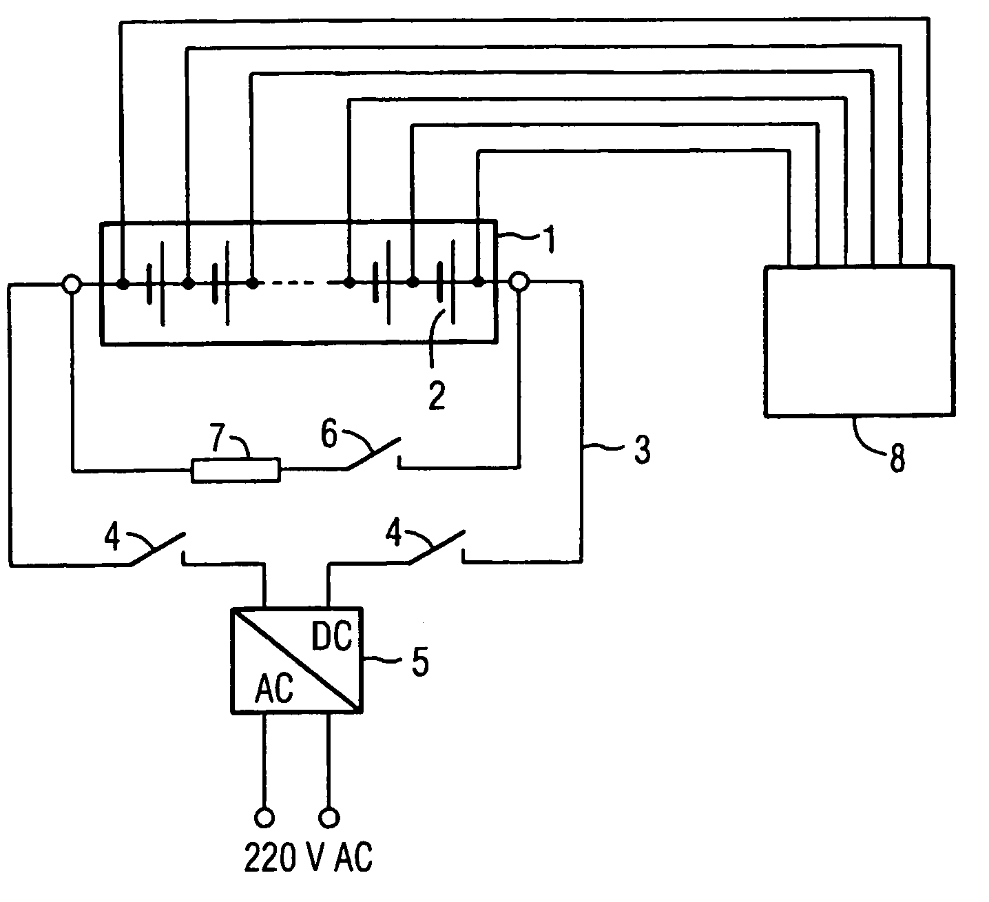
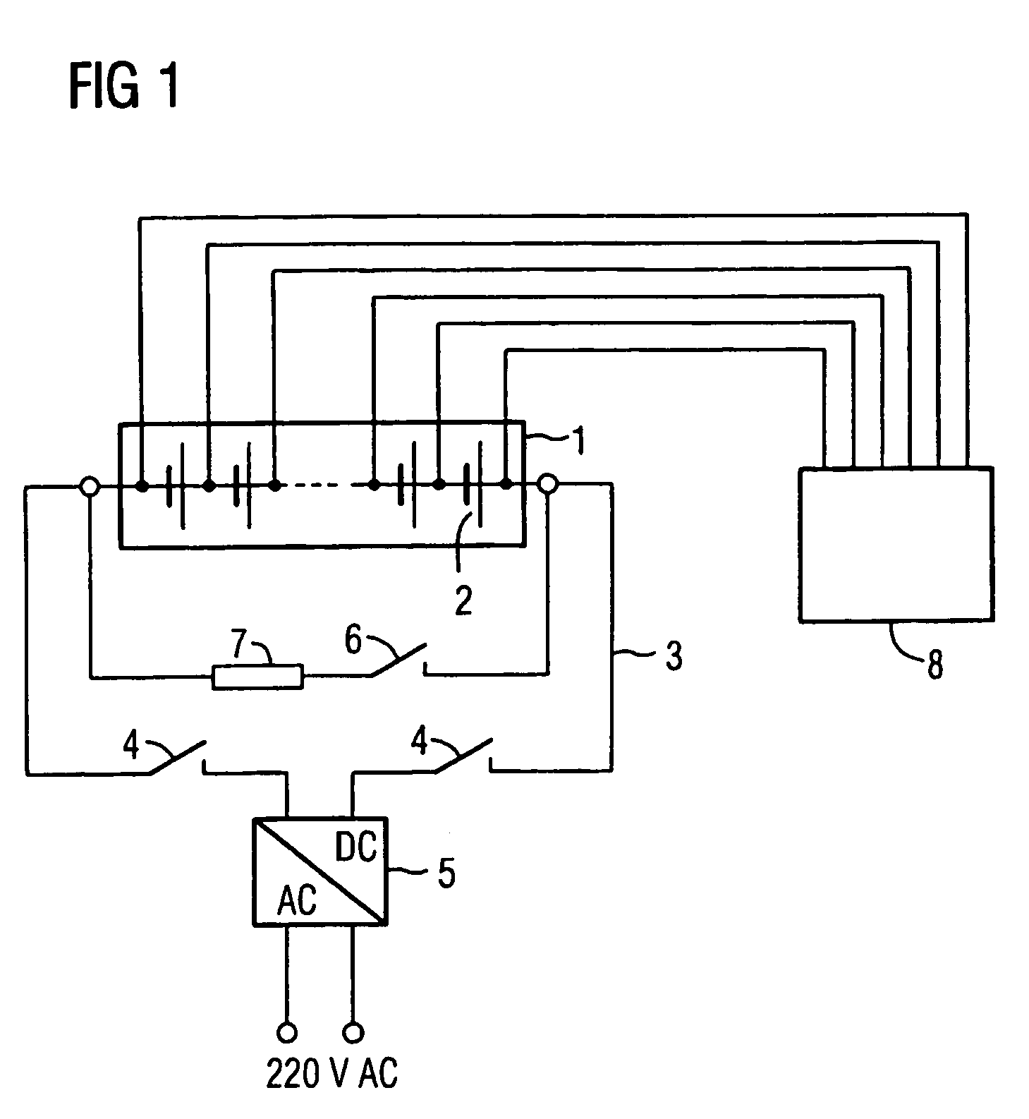
[0023]FIG. 1 shows a fuel cell stack or a fuel cell battery 1 with a number of individual PEM fuel cells 2. A controllable power supply or a DC voltage source 5 is connected to the fuel cell stack 1 via supply lines 3 and two switches 4. A discharge resistance 7, which can be switched via a switch 6, is also connected to the fuel cell stack 1. A voltmeter 8 is provided in order to carry out the cell voltage measurements, and is connected individually to all of the PEM fuel cells 2.

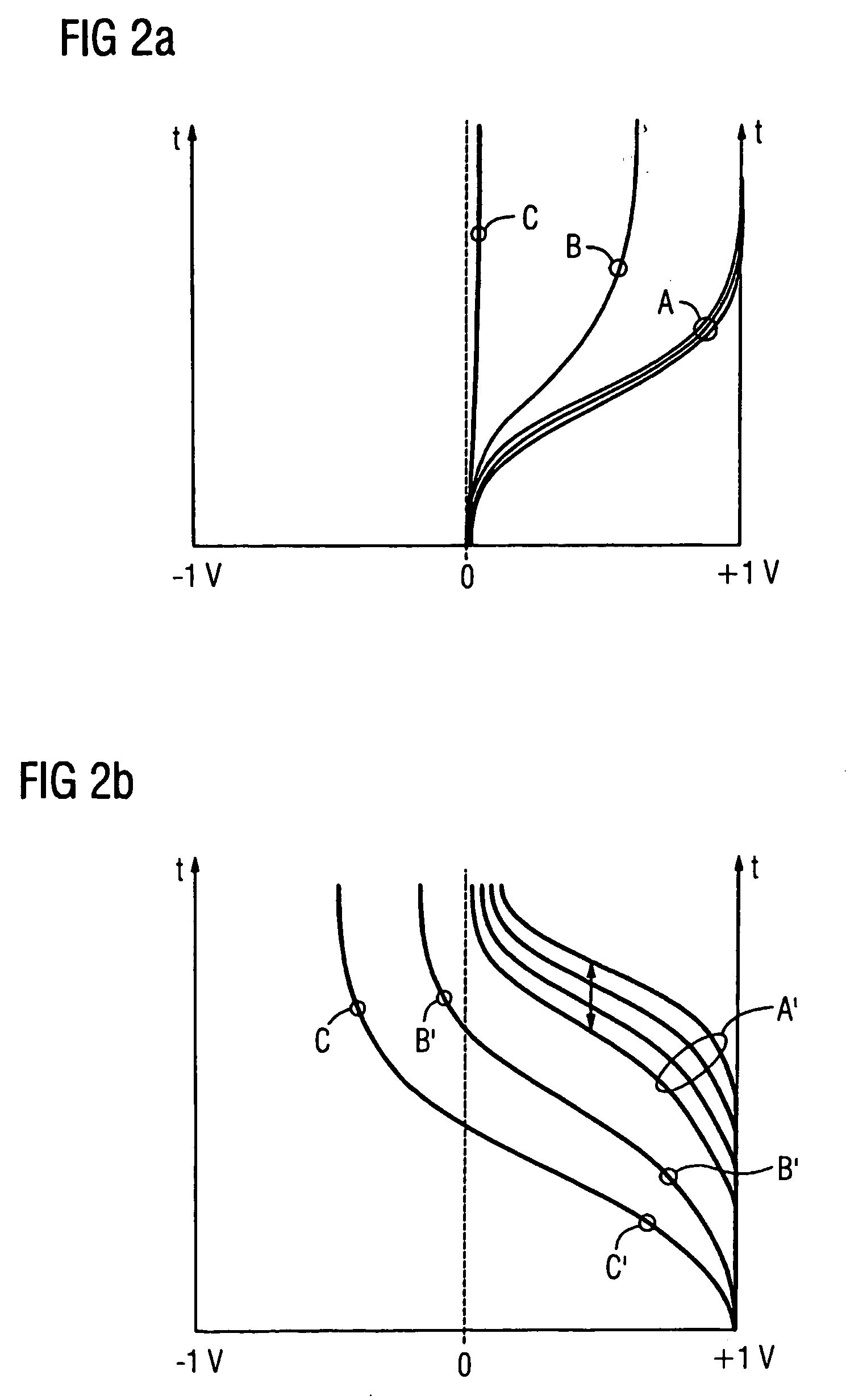
[0024] The process of carrying out the leak test method is illustrated, in particular, in FIGS. 2a, b. The gas areas of the individual PEM fuel cells 2 have moisture, that is to say a water content, on both the anode side and the cathode side before the start of the leak test method. The fuel cells 2 are, however, in this case not flooded with water.

[0025] At the start of the leak test method,...


PUM


Abstract

A method is for detecting a gas leak between the anode gas region and the cathode gas region of a PEM fuel cell. According to the method, a) the fuel cell is charged with a direct current, and b) the temporal course of the electrical voltage on the fuel cell is measured. Using only a small amount of equipment, a leak test can be carried out on a fuel cell stack. The test is highly sensitive even to extremely small leaks, but can also be used for large leaks, and indicates the exact position of defective fuel cells within the fuel cell.

Description

[0001] This application is the national phase under 35 U.S.C. § 371 of PCT International Application No. PCT / EP03 / 04269 which has an International filing date of Apr. 24, 2003, which designated the United States of America and which claims priority on European Patent Application number EP 02010338.8 filed May 7, 2002, the entire contents of which are hereby incorporated herein by reference.FIELD OF THE INVENTION [0002] The invention generally relates to a method for determination of a gas leak, preferably between the anode gas area and the cathode gas area, in a PEM fuel cell. BACKGROUND OF THE INVENTION [0003] A PEM fuel cell (PEM=Polymer Electrolyte Membrane) has a polymer membrane, which conducts ions, as the electrolyte. A gas-permeable, porous, electrically conductive collector is arranged in each case on the anode side and on the cathode side on both sides of the membrane, with a catalyst in a finely distributed form being located between the collector and the membrane. [0004]...

Claims


Application Information

Patent Timeline
IPC IPC(8): H01M8/00H01M8/04H01M8/10
CPCH01M8/04223H01M8/04238H01M8/04246H01M8/04559Y02E60/50H01M8/0488H01M8/0491H01M8/04977H01M2300/0082H01M8/04679H01M8/04952H01M8/241H01M8/2457H01M8/04225
Inventor COERLIN, DETLEYGELLERT, HARRYSTUHLER, WALTER
Owner SIEMENS AG
Why Eureka
Try Eureka