Electric junction box and connection structure of tuning fork terminal

a technology of tuning fork terminals and junction boxes, which is applied in the direction of connection contact material, fixed connection, coupling device connection, etc., can solve the problems of required soldering process, achieve the effect of simplifying the terminal shape, preventing connection failure, and easy insertion into the slo

Inactive Publication Date: 2006-02-16
SUMITOMO WIRING SYST LTD
View PDF9 Cites 17 Cited by
  • Summary
  • Abstract
  • Description
  • Claims
  • Application Information

AI Technical Summary

Benefits of technology

[0032] As described above, forming the contact portions of the slot on the same flat surface of the conducting plate base prevents deformation of the tuning-fork terminal. The form further ensures prevention of connection failure due to deformation and vibration, since the locking and contact portions are closely located when the mating tab-shaped terminal and the tuning-fork terminal are interlocked.
[0033] In the embodiments of the present invention, making the lower surface of the latching tab tapered allows easy in

Problems solved by technology

And, since terminals 5 of control circuit board 4 and terminals 2 of the bus bars are s

Method used


Image

  • Electric junction box and connection structure of tuning fork terminal
  • Electric junction box and connection structure of tuning fork terminal
  • Electric junction box and connection structure of tuning fork terminal

Examples


case 11

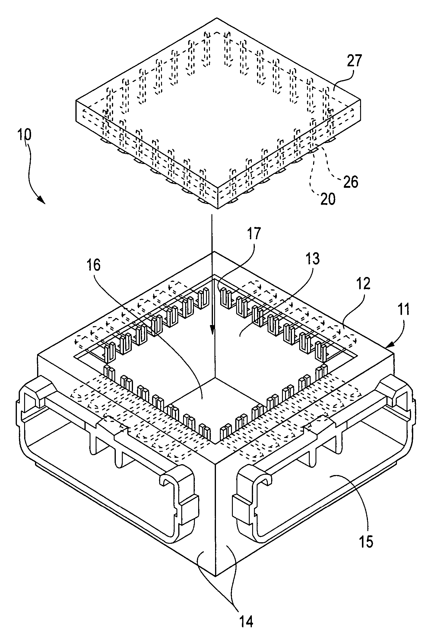
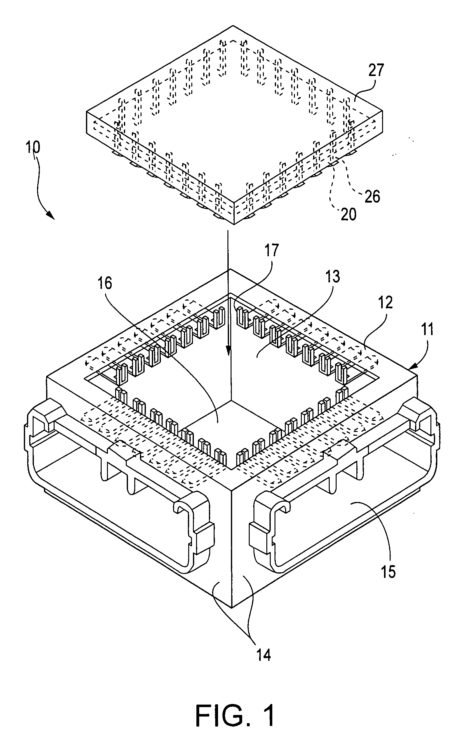
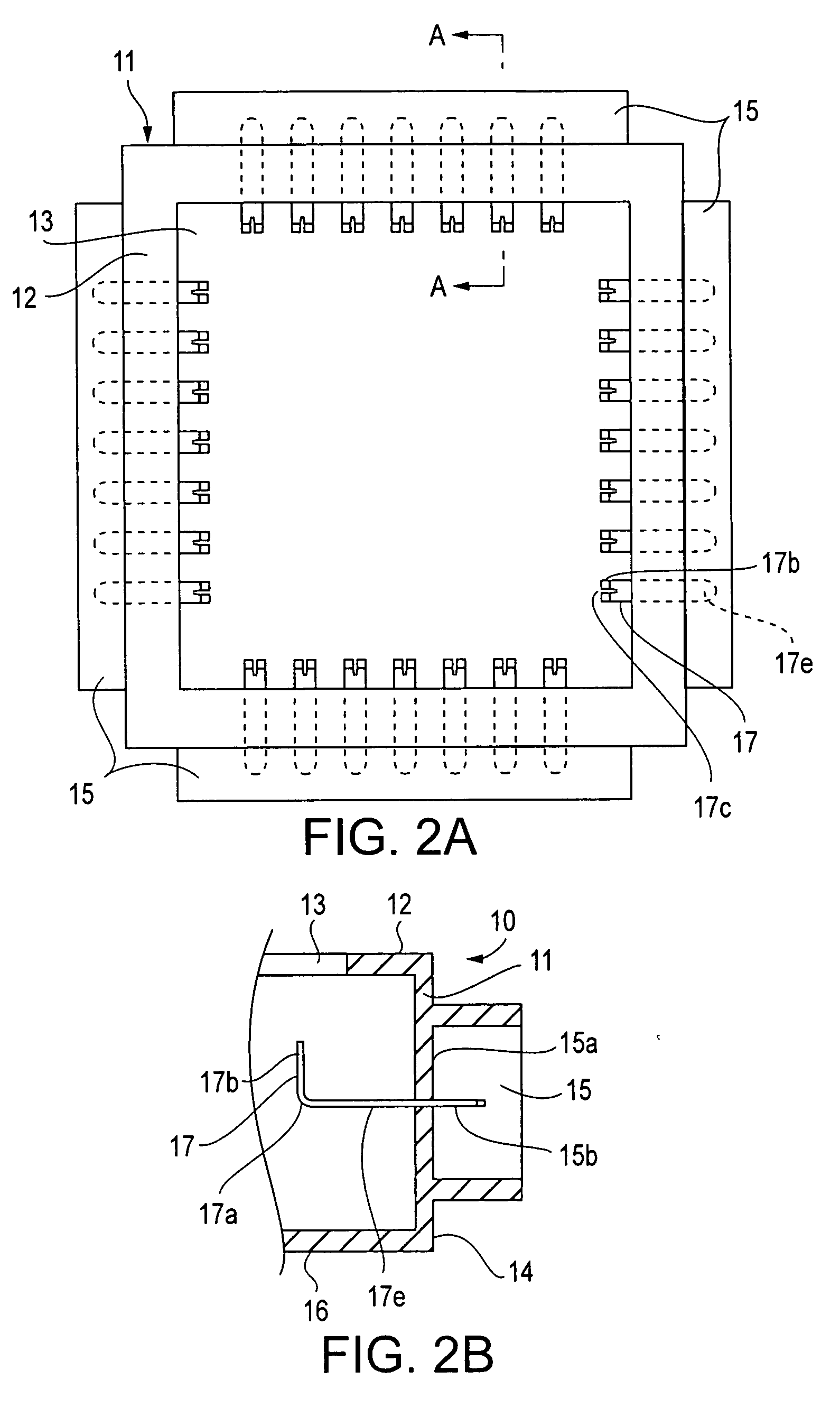
[0060] Case 11 is a rectangular-shaped box, having square-shaped opening 13 provided on upper side 12. Case 11 also has one connector joint 15 projecting from each of the four outer sides of peripheral walls 14. Bottom wall 15a of connector joint 15 has terminal holes 15b that are equally spaced in a single row. Alternatively, the terminal holes 15b may be provided in other predetermined spacing arrangements. In the present embodiment, lower side 16 of case 11 is a closed side.

[0061] A plurality of terminals 17 are housed within case 11. As shown in FIG. 3, terminal 17 is L-shaped, bending at a substantially 90 degree angle at bending portion 17a in a central region in the length direction. Press-connecting slot 17c is formed by cutting out a portion from the tip center of a first end 17b through bending portion 17a. Contact portions 17d are provided in a projecting manner, with the two inner sides of press-connecting slot 17c facing each other. A second end 17e has locking hole 17f...

first embodiment

[0072] On printed-circuit board 20 according to the present embodiment, unlike the first embodiment, conductor 22 is formed in accordance with a predetermined circuit pattern as shown in FIG. 9. A special printed-circuit board is thus provided for each specific circuit pattern. Furthermore, as shown in FIG. 10, connection pins 26 are press fitted with printed-circuit board 20 as press-fit terminals. In other words, a copper coating is applied to the entire inner peripheral surface of terminal hole 23 of printed-circuit board 20 and to the surface of printed-circuit board 20, while a tin coating or a solder coating is applied to the copper coated surface to form conductive layer 28, thereby connecting conductive layer 28 and conductor 22. Connection pin 26 has press-fit portion 26b that is stamped to a thin plate. Press-fit portion 26 is press-fitted into terminal hole 23 of printed-circuit board 20 to establish connection with conductor 22.

[0073] According to the above embodiment, b...

fourth embodiment

[0078]FIGS. 13, 14, and 15 illustrate a connection structure of tuning-fork terminal 111 according to the present invention. Tuning-fork terminal 111 is provided at the end of bus bar 110 (conducting plate) housed in electric connection box 130 and connected to relay terminal 121 of relay 120 fitted into relay mount 132 formed on upper wall 131 of electric connection box 130.

[0079] In particular, tuning-fork terminal 111 is formed at the end portion of base 110a of bus bar 110 bent vertically as shown in FIG. 14, including horizontal portion 112 on the same surface of base 110a of bus bar 110 and vertical portion 113 that continues from horizontal portion 112 through bend 114. Vertical portion 113 has press connection slot or crimping slot 115 vertically notched from the center of the end to bend 114 and contact portions 116 projecting from both inner sides of slot 115 and directed toward each other. Horizontal portion 112 has latching hole 117 horizontally notched from bend 114 tow...


PUM


Abstract

An electric junction box that can accommodate various circuit patterns in accordance with a combination of a printed-circuit board and a case housing the printed-circuit board. Connection pins connected to conductors are provided in a projecting position at intervals along the peripheral edge of a printed-circuit board. An opening corresponding to the printed-circuit board is formed in a central region of the upper side of a case. Connector joints are positioned on the peripheral walls of the four sides of the case, and L-shaped terminals are provided at the same intervals as for the connection pins along the opening. Additionally, a connection structure of a tuning-fork terminal includes a tuning-fork terminal at the end portion of a conducting plate base bent vertically and having a press connection slot in the center of the vertical portion; and a tab-shaped mating terminal electrically connected to contact portions projecting from inner sides of the slot.

Description

CROSS-REFERENCE TO RELATED APPLICATIONS [0001] The present disclosure relates to subject matter contained in priority Japanese Application Nos. 2004-242564, filed on Aug. 23, 2004, and 2004-236774, filed on Aug. 16, 2004, which are herein expressly incorporated by reference in their entireties. BACKGROUND OF THE INVENTION [0002] 1. Field of the Invention [0003] The present invention relates to an electric junction box that can be used to make a variety of circuit connections between electric wires connected to connectors via a printed-circuit board. In particular, the present invention relates to an electric junction box that is well-suited to use in an automobile. The present invention further relates to a connection structure of a tuning-fork terminal, particularly to a structure that secures the tuning-fork terminal to an electrically connected mating terminal. [0004] 2. Description of the Related Art [0005] Conventionally, an electric junction box, having a configuration in whic...

Claims


Application Information

Patent Timeline
IPC IPC(8): H01R4/66
CPCH01R12/58H01R13/112H01R13/6658H05K1/0287H05K3/308H05K2201/09681H05K2201/10189H05K2201/1059
Inventor SEKIDO, TOSHIHISA
Owner SUMITOMO WIRING SYST LTD
Why Eureka
Try Eureka