Timing belt tensioner with stops controlled by frictional brake

a frictional brake and belt tensioner technology, applied in mechanical equipment, ropes and cables for vehicles/pulleys, gears, etc., can solve the problems of reducing the service life of the backstop, affecting the service life of the belt, so as to reduce manufacturing and installation time and cost, and facilitate installation. , the effect of simplifying construction

Active Publication Date: 2006-02-16
LITENS AUTOMOTIVE INC
View PDF17 Cites 43 Cited by
  • Summary
  • Abstract
  • Description
  • Claims
  • Application Information

AI Technical Summary

Benefits of technology

[0012] The frictional brake resists arm movement towards the minimum belt take-up position caused by belt forces at a level such as that resulting from the crankshaft being turned backwards, but “releases” and allows the backstop to rotate toward the minimum belt take-up position when the pivot arm is rotated manually, e.g., during installation. The configuration of the tensioner according to the invention permits easy installation, simplifies construction, and hence reduces manufacturing and installation time and cost.
[0013] According to another aspect of the invention, rotary apparatus for selectively transmitting rotary power or torque includes a pair of rotary members which are axially interconnected direc...

Problems solved by technology

In other words, the backstop is designed to prevent tooth skip, which tooth skip would otherwise cause timing errors between the various sprockets and, consequently, equipment errors and damage.
The common practice of placing the backstop at a certain distance from the nominal pivot arm position is not feasible for tensioners which provide no initial manual installation adjustment and with which the rotation of the pivoted structure is intended to compensate for engine build tolerances.
In addition, the increased life expectancy of modern engine components results in longer belt life and belt stretch, and hence generally greater adjustment ranges are required for the pivoted structure of the tensioner during the life of the tensioner.
In each of these patents, however, the tensioner arm is unable to rotate away from the belt...

Method used


Image

  • Timing belt tensioner with stops controlled by frictional brake
  • Timing belt tensioner with stops controlled by frictional brake
  • Timing belt tensioner with stops controlled by frictional brake

Examples


Embodiment Construction

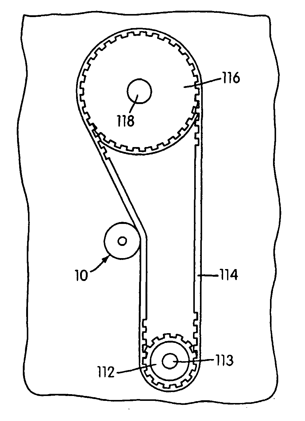
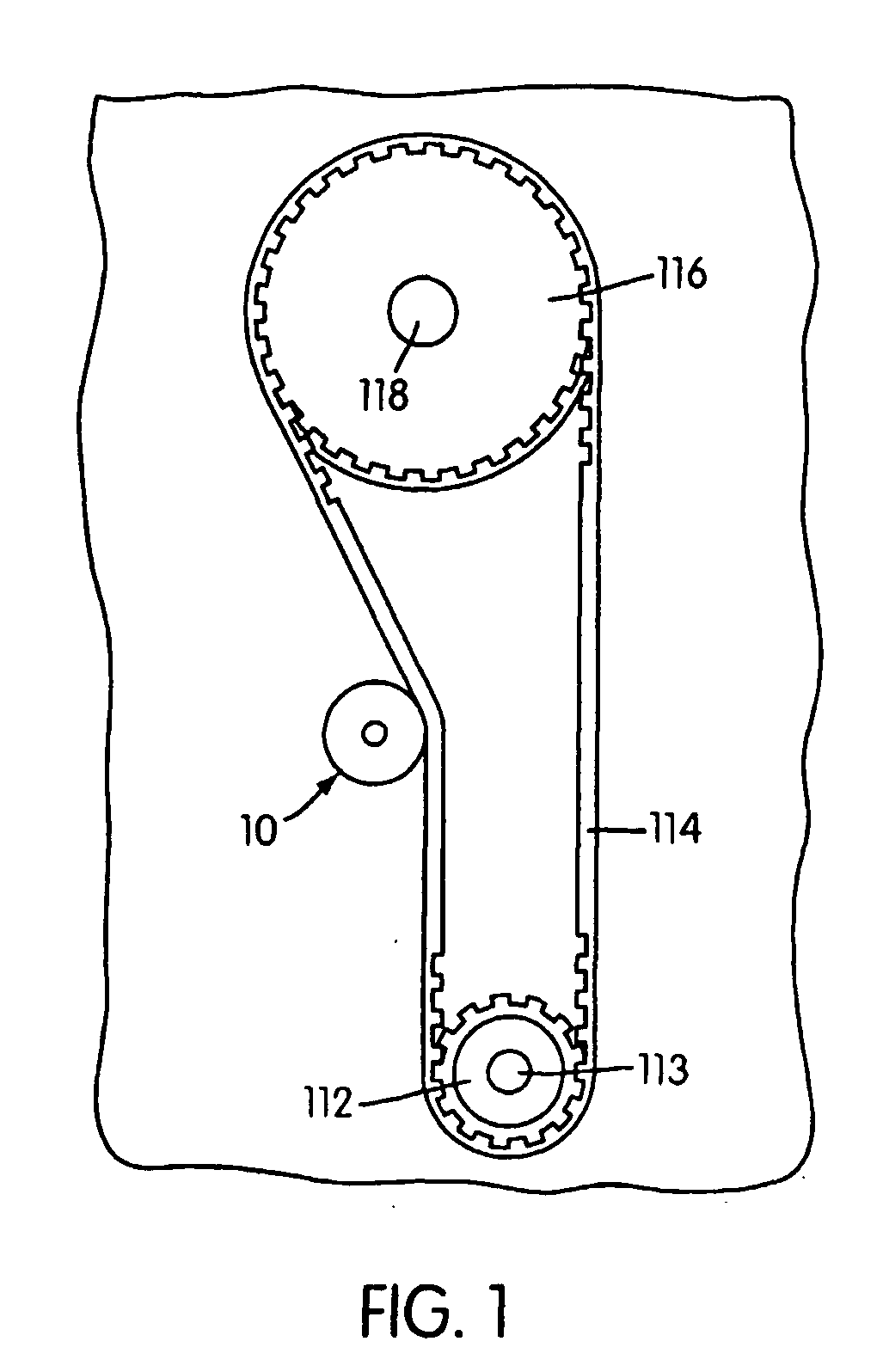
[0026] A timing belt system for an internal combustion engine is illustrated in FIG. 1. A toothed, pulley sprocket 112 is fixed to the crankshaft 113 of the engine, and an internally toothed belt 114 is driven by the sprocket 112. The toothed belt 114 is trained about (and hence drives) a second, externally toothed sprocket 116, which sprocket 116 is fixed to (and hence causes to rotate) a cam shaft 118 of the engine. A tensioner 10 according to the invention is mounted in tensioning relation with the belt 114.

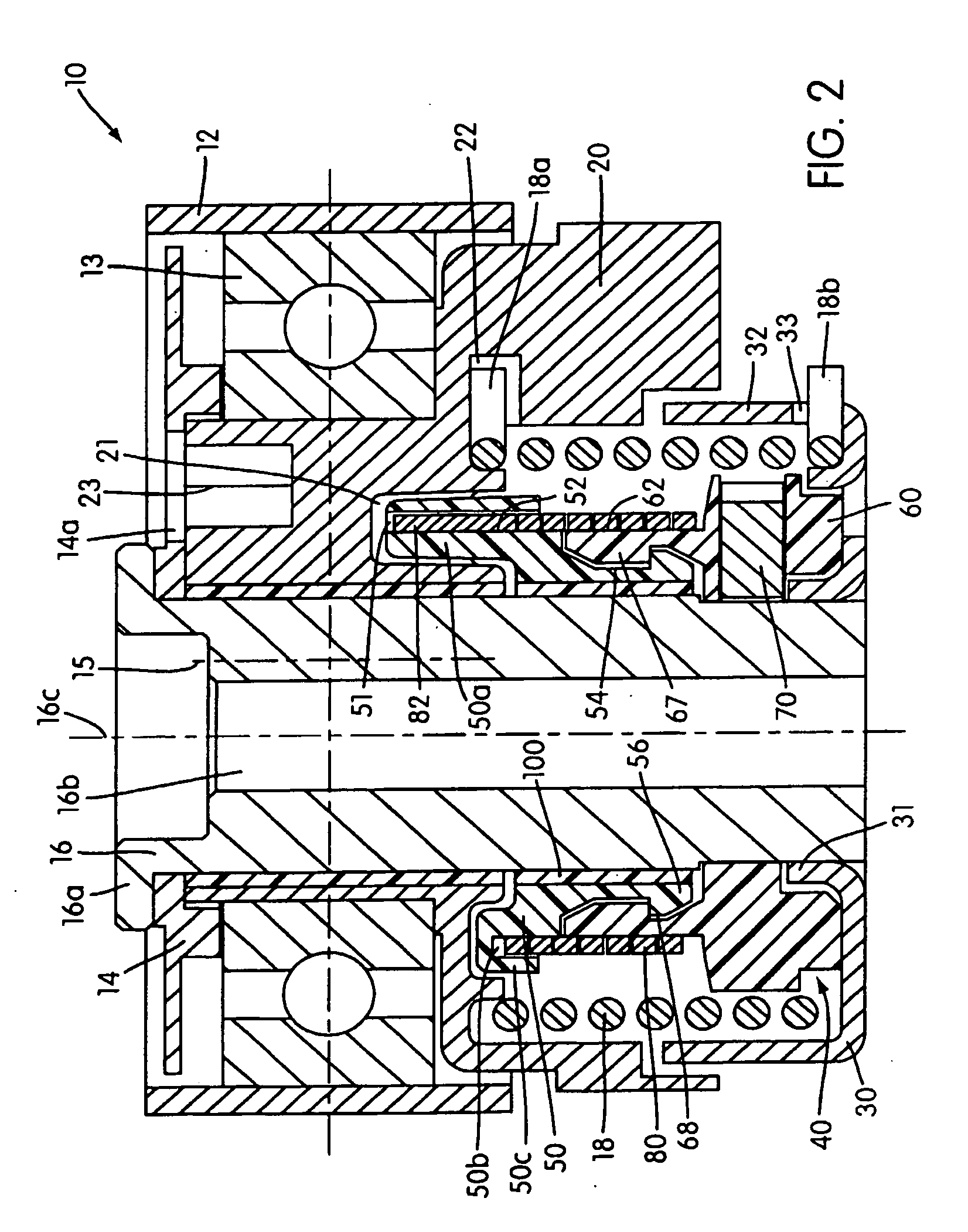
[0027] As illustrated in FIG. 2, the tensioner 10 generally consists of a pulley 12 that is mounted on a ball bearing assembly 13 which extends circumferentially around a pivot arm 20, and the pivot arm 20 is eccentrically pivotally mounted on a pivot shaft 16, e.g., by means of a journal. In other words, the pulley 12 rotates around its own axis of rotation 15 extending through the center of the ball bearing assembly 13, and the pivot arm 20 pivots (with the pulley 12 pivoti...


PUM


Abstract

A tensioner (10) features a backstop device (40) which allows free rotation of the pivot arm (20) in one direction but not the other. Reverse rotation is prevented by friction that is able to resist torque on the pivot arm (20) under ordinary operating conditions which otherwise could permit belt tooth-skip to occur. In disclosed embodiments, the backstop device (40) includes a stop sleeve (50) and a clamp holder (60) which are axially interlocked and are able to rotate relative to each other. A clutch spring (80) surrounds permits relative rotation between the stop sleeve (50) and the clamp holder (60) in one direction but not the other. A clamp (70) retained within the clamp holder (60) frictionally engages the pivot shaft. A viscous coupling may be used in place of the frictional clamp.

Description

FIELD OF THE INVENTION [0001] The invention relates in general to automotive belt tensioners and, in particular, to a timing belt tensioner in which the position of the arm backstop is controlled by a one-way clutch and a frictional brake. BACKGROUND OF THE INVENTION [0002] Automotive belt tensioners are well known in the art and have been used to regulate tension in various belt systems, e.g., timing belts. In general, a belt tensioner includes a movable support structure that rotatably supports a portion of a belt in an engine or other mechanical system. The rotational position of the arm / pulley sub-assembly of a belt tensioner normally self-adjusts to compensate for increases or decreases in belt path length due to the thermal expansion or contraction of the engine and / or belt wear and stretch, thereby regulating tension in the belt. Additionally, the entire tensioner assembly is normally manually adjustable relative to the engine block so that the tensioner can be adjusted to th...

Claims


Application Information

Patent Timeline
IPC IPC(8): F16G9/00F16D41/20F16H7/08F16H7/12
CPCF16D41/206F16H7/0831F16H7/0834F16H2007/084F16H7/129F16H2007/081F16H7/1218F16D41/20F16H7/12
Inventor LEHTOVAARA, JORMA J.STEPNIAK, JACEKFRANKOWSKI, MAREKLIPOWSKI, MATSKFORREST, RICHARDA
Owner LITENS AUTOMOTIVE INC
Why Eureka
Try Eureka