Lightened turbomachine blade and its manufacturing process

a turbomachine blade and manufacturing process technology, applied in the field of turbomachine blades, can solve the problems of increased cavity volume, reduced mechanical strength and life of the blade, and increased cavity volume, so as to reduce the amount of welding to be done, increase the mechanical strength and the lifetime of the blade, and reduce the cost of the componen

Inactive Publication Date: 2006-02-23
SN DETUDE & DE CONSTR DE MOTEURS DAVIATION S N E C M A
View PDF9 Cites 37 Cited by
  • Summary
  • Abstract
  • Description
  • Claims
  • Application Information

AI Technical Summary

Benefits of technology

[0011] Such a blade is noteworthy in that the weld bead emerges on the hollowed side and penetrates the airfoil with a depth P at least equal to the thickness EC of the edge of the cover so as to provide continuity of the material between the edge of the cover and the rest of the airfoil over a depth at least equal to the thickness EC of the edge of the cover.
[0012] Such an arrangement helps to increase the mechanical strength and the lifetime of the blade. This is because the continuity of material eliminates any slit in the vicinity of the hollowed side and perpendicular to it, which may exist between the cover and the rest of the airfoil, such slits constituting crack initiators liable to propagate along the hollowed side owing to the effect of the mechanical stresses generated near the hollowed side and directed tangentially to this side.
[0013] Advantageously, the width LC of the cavity is at least equal to half the width LP of the airfoil, the width of the airfoil LP being taken between the leading edge and the trailing edge along the geometrical neutral line passing at mid-distance between the sides, the width LC of the cavity being taken between the lateral surfaces along the same geometrical neutral line. Such an arrangement makes it possible to achieve substantial lightening with a single cavity closed off by a single cover, thereby reducing the amount of welding to be done, and consequently the cost of the component.

Problems solved by technology

Such blades have very thin airfoils that are subject to alternating tensile and compressive stresses that are liable to fracture them by the appearance and propagation of cracks in their sides.
The drawback of this technology is that substantial lightening results in an increase in the volume of the cavities and as a consequence the blade is weakened and made more flexible.
This technology makes it possible to obtain blades of very high performance, but the manufacturing process has the drawback of being lengthy and expensive.
However, this technology has the drawback that a large amount of material is left between the holes and the blade requires a very substantial amount of welding, since each hole / plug pair must be welded around its entire periphery.
The problem to be solved is how to design a structure and a process for the reliable and inexpensive manufacture of lightened blades, the blades having to be of high performance in terms of lightness and mechanical strength.

Method used


Image

  • Lightened turbomachine blade and its manufacturing process
  • Lightened turbomachine blade and its manufacturing process
  • Lightened turbomachine blade and its manufacturing process

Examples


Embodiment Construction

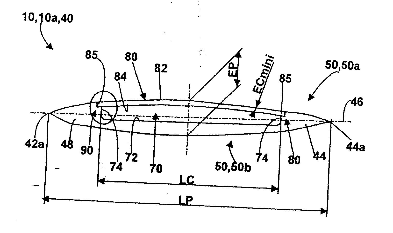
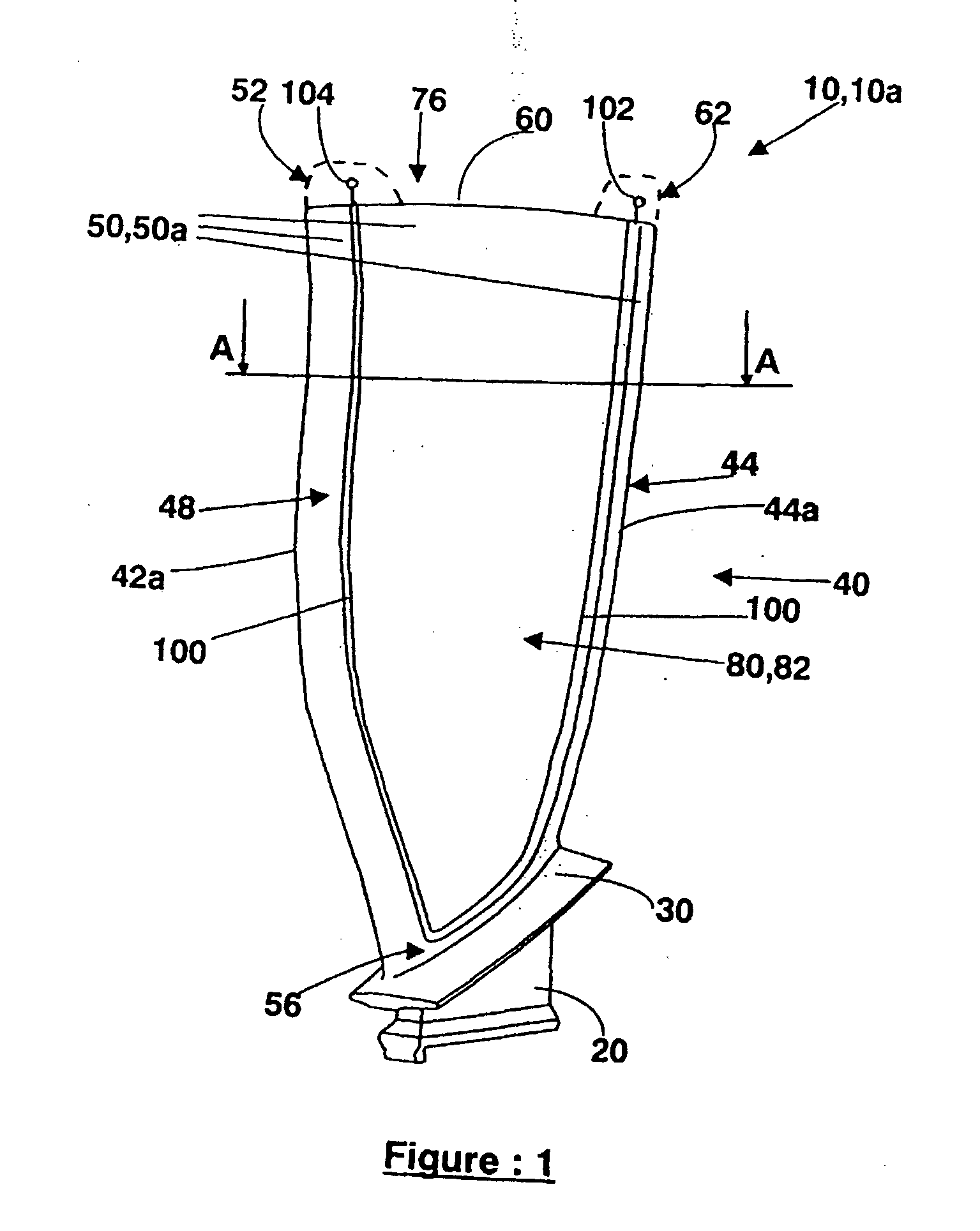
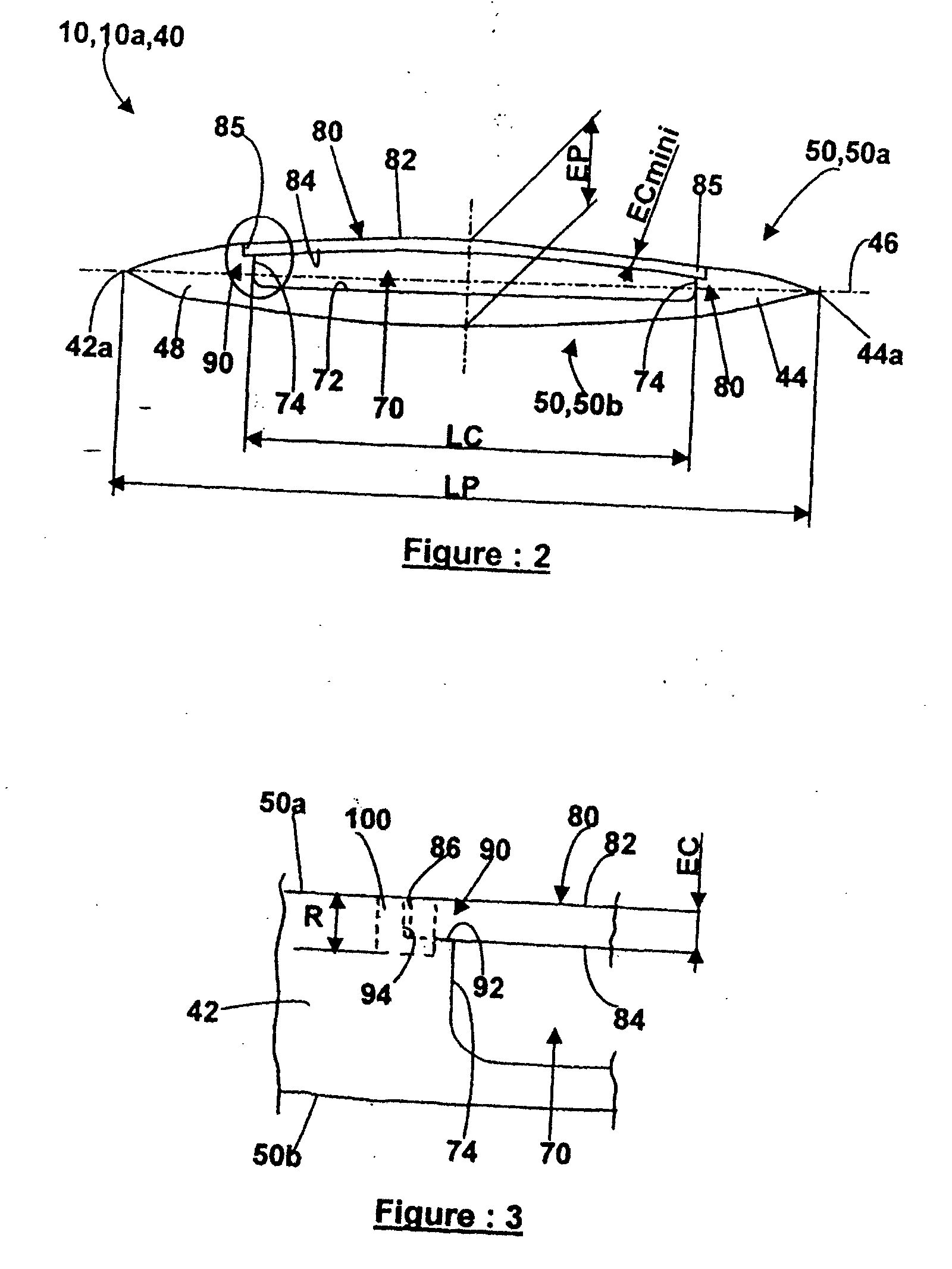
[0038] Reference will firstly be made to FIG. 1. The blade 10 is a well-known object comprising, in succession from the bottom up in FIG. 1: a root 20 via which it is fitted into a rotor (not shown), a platform 30 and a airfoil 40. The airfoil 40 is thin and cambered. The airfoil 40 is bonded laterally at the front by a rounded edge called the leading edge 42, at the rear by a second, slimmer, edge called the trailing edge 44 and laterally by two sides 50. The base of the airfoil 40, that is to say that part of the airfoil 40 against the platform 30, will be denoted by 56 and the tip of the airfoil 40, that is to say that end of the airfoil 40 on the opposite side from the platform 30, will be denoted by 60. In addition, the line constituting the end of the leading edge 42 will be denoted by 42a and the line constituting the end of the trailing edge 44 will be denoted by 44a. The airfoil 40 is cambered, that is to say it forms, between the leading edge 42 and the trailing edge 44, a...


PUM

PropertyMeasurementUnit
thicknessaaaaaaaaaa
shapeaaaaaaaaaa
thickness ECaaaaaaaaaa

Abstract

A turbomachine blade includes a metal alloy airfoil having a cavity closed off by a cover on a hollowed side, the cover providing aerodynamic continuity of the hollowed side and being bonded via an edge thereof to the rest of the airfoil by a weld bead. The weld bead emerges on the hollowed side and penetrates into the airfoil to a depth P at least equal to the thickness EC of the edge of the cover so as to provide continuity of material between the edge of the cover and the rest of the airfoil over a depth at least equal to the thickness EC of the edge of the cover. A process for manufacturing such a blade is also disclosed.

Description

TECHNICAL FIELD OF THE INVENTION [0001] The invention relates to turbomachine blades and more particularly to a structure and to a process for manufacturing lightened, hollow metal blades intended, for example, for compressor or fan rotors of bypass turbojets for propelling aircraft. PRIOR ART AND PROBLEM SOLVED BY THE INVENTION [0002] So as not to burden the description, the constituents of the blade are denoted and referenced in the same way in the case of a blank blade and in the case of a finished blade. [0003] Turbojet components used in aeronautics must combine characteristics of lightness, high vibration resistance and high fatigue resistance. This is the case in particular with the blades mounted around the periphery of bladed compressor or fan rotors. Such blades have very thin airfoils that are subject to alternating tensile and compressive stresses that are liable to fracture them by the appearance and propagation of cracks in their sides. Moreover, the process for manufa...

Claims


Application Information

Patent Timeline
Patent Type & Authority Applications(United States)
IPC IPC(8): B64C11/24F01D5/16B21D53/78B23K20/12B23P15/04F01D5/14F01D5/18F02C7/00F04D29/38
CPCB23K20/122B23P15/04F01D5/147Y10T29/49339Y02T50/671Y02T50/673Y02T50/676F01D5/18Y02T50/60
Inventor FERTE, JEAN-PIERREBOUR, JEAN-LUCLARROUQUERE, DENIS
Owner SN DETUDE & DE CONSTR DE MOTEURS DAVIATION S N E C M A
Why Eureka
Try Eureka