
Eureka
For R&D, Eureka makes reading and utilizing patents & technical documents easy.
Eureka AIR
Designed for self-driven R&D workflows. Generate viable solutions, solve complex R&D challenges, empower your innovation with AI.

Eureka Materials
Designed for material experts only. Revolutionize your material R&D, from search, analyze, to developing new materials.

TechResearch
Generate reliable direction feasibility study reports for your R&D in just a few steps.

TechSeek
Discover and master advanced knowledge NOW. Basics, ideas, possibilities, all at once.

TechMind
As an expert in R&D Theories, TechMind can generates customized viable solutions instantly.

TechRisk
Analyze your overall solution with one click, know your potential R&D risks in advance.

TechMonitor
Get weekly tech updates, stay abreast of the latest tech innovations and key insights.
Heat pipe
- Summary
- Abstract
- Description
- Claims
- Application Information
AI Technical Summary
Benefits of technology
Problems solved by technology
Method used
Image

Examples
first embodiment
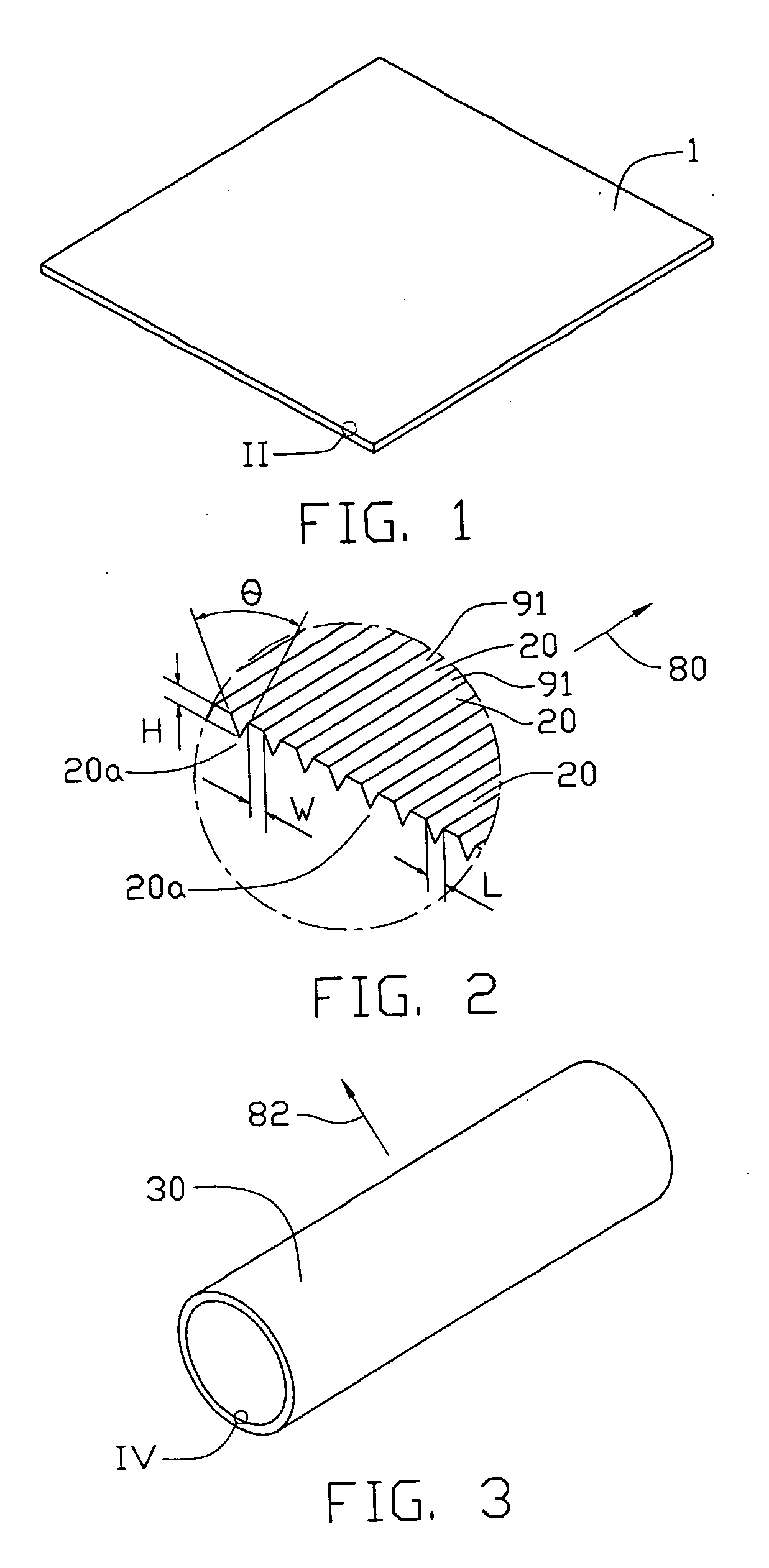
[0022] In a first embodiment, referring FIGS. 9 and 10, a thermal assembly 90 may generally be composed of a heat pipe 92, a central processing unit 98, and a heat sink 93. Futher, the heat pipe 92 may generally include a metal tube (e.g., copper) 94 and an amount of fluid 96 sealed in the metal tube 94. The metal tube 94 may usefully be composed of copper or an alloy thereof or, alternatively, be a metal tube made of a metal such as aluminum, iron or stainless steel. Advantageously, the material chosen for metal tube 94 is readily formable, has good thermal conductivity, and is generally corrosion resistant.
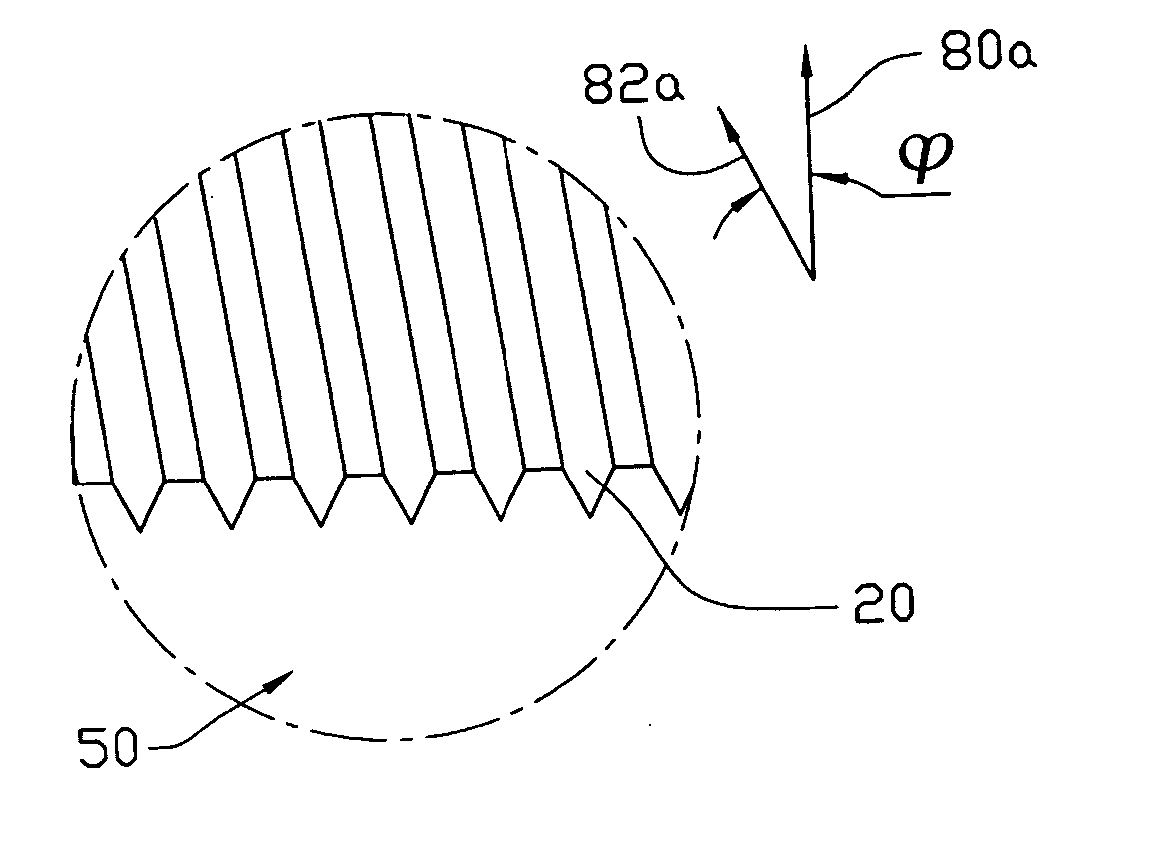
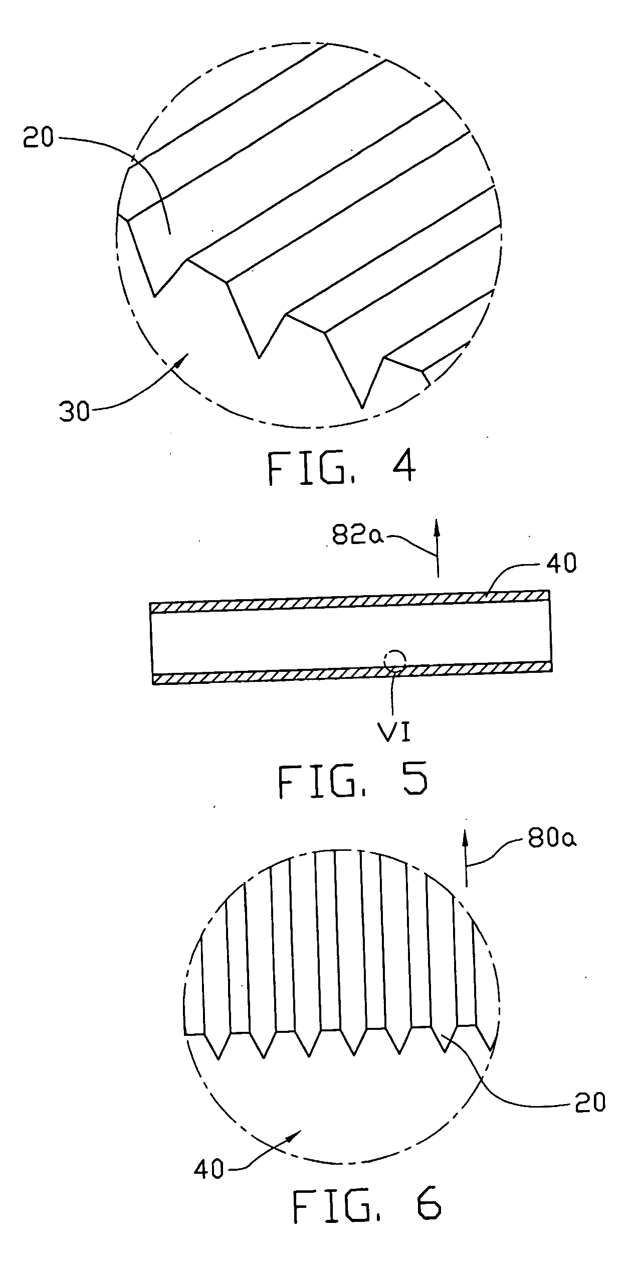
[0023] The metal tube 94 has an inner surface 94a. Referring also to FIG. 2, the inner surface 94a may be patterned to define at least one pitch 91 and at least two grooves 20. A given pitch 91 may separate adjacent grooves 20. The grooves 20 may be, for example, screw threads on the inner surface 94a of the metal tube 94.
[0024] Preferably, the inner surface 94a of the metal tu...
second embodiment
[0032] Alternatively, the stamper can be formed as follows (process not illustrated). A pattern is designed. The designed pattern corresponds to a pattern of a groove 20. A nickel substrate is provided. A photoresist layer is coated on the nickel substrate. The coated photoresist layer serves as a mask on the nickel substrate. The mask is exposed and developed by the lithography technique of the The mask is then partially removed, thereby partially exposing the nickel substrate. Such a mask exposes the nickel substrate. The exposed nickel substrate has the designed pattern serving as the pattern of a groove 20. The nickel substrate and the mask collectively serve as the stamper.
[0033] The process of transferring the pattern onto the metal plate may further include a printing step (not shown). In such step, the pattern of the stamper is printed onto the metal plate 1. The pattern is printed by a nano-imprinting technique or alternatively by a hot-embossing technique. In the hot-embo...
PUM
 Abstract
Description
Claims
Application Information
 - R&D Engineer
- R&D Manager
- IP Professional
- Industry Leading Data Capabilities
- Powerful AI technology
- Patent DNA Extraction
Browse by: Latest US Patents, China's latest patents, Technical Efficacy Thesaurus, Application Domain, Technology Topic, Popular Technical Reports.
© 2024 PatSnap. All rights reserved.Legal|Privacy policy|Modern Slavery Act Transparency Statement|Sitemap|About US| Contact US: help@patsnap.com