Light emitting apparatus

a technology of light emitting apparatus and light source, which is applied in the direction of discharge tube/lamp details, discharge tube luminescent screens, discharge tubes/lamp details, etc., can solve the problems of low light emitting efficiency, low color rendering properties, and the emitting apparatus is not capable of blending light satisfactorily, etc., to achieve a wide range of colors and low power consumption

Active Publication Date: 2006-03-02
NICHIA CORP
View PDF7 Cites 51 Cited by
  • Summary
  • Abstract
  • Description
  • Claims
  • Application Information

AI Technical Summary

Benefits of technology

[0013] With the background described above, the present invention has an object to provide a light emitting

Problems solved by technology

Since the emission from the ultraviolet LED is hardly visible to the eye, ultraviolet ray that has leaked cannot be used as light and results in low light emitting efficiency.
The third light emitting apparatus is not capable of blending light satisfactorily, and has low color rendering properties.
Si

Method used


Image

  • Light emitting apparatus
  • Light emitting apparatus
  • Light emitting apparatus

Examples


first embodiment

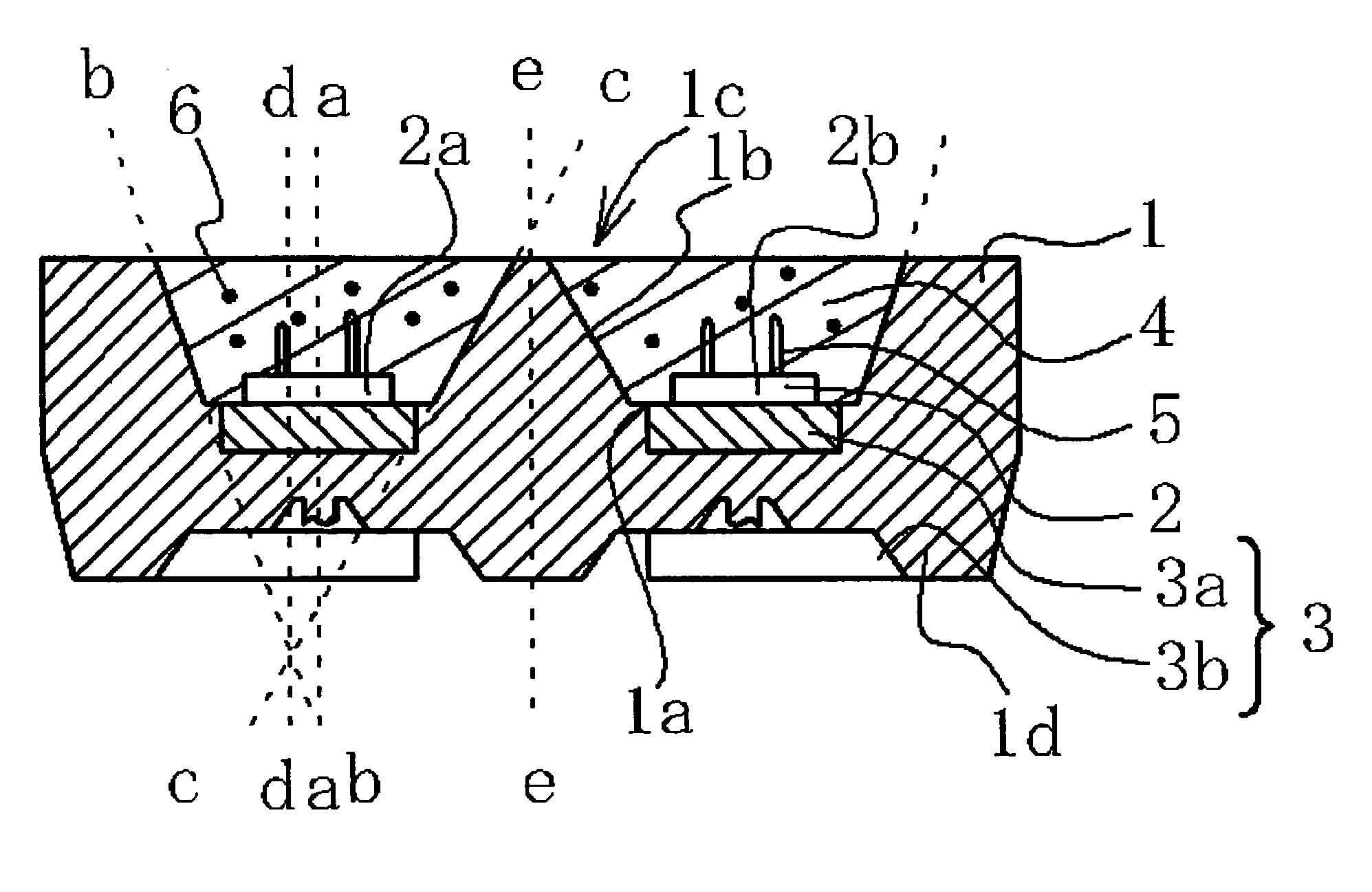
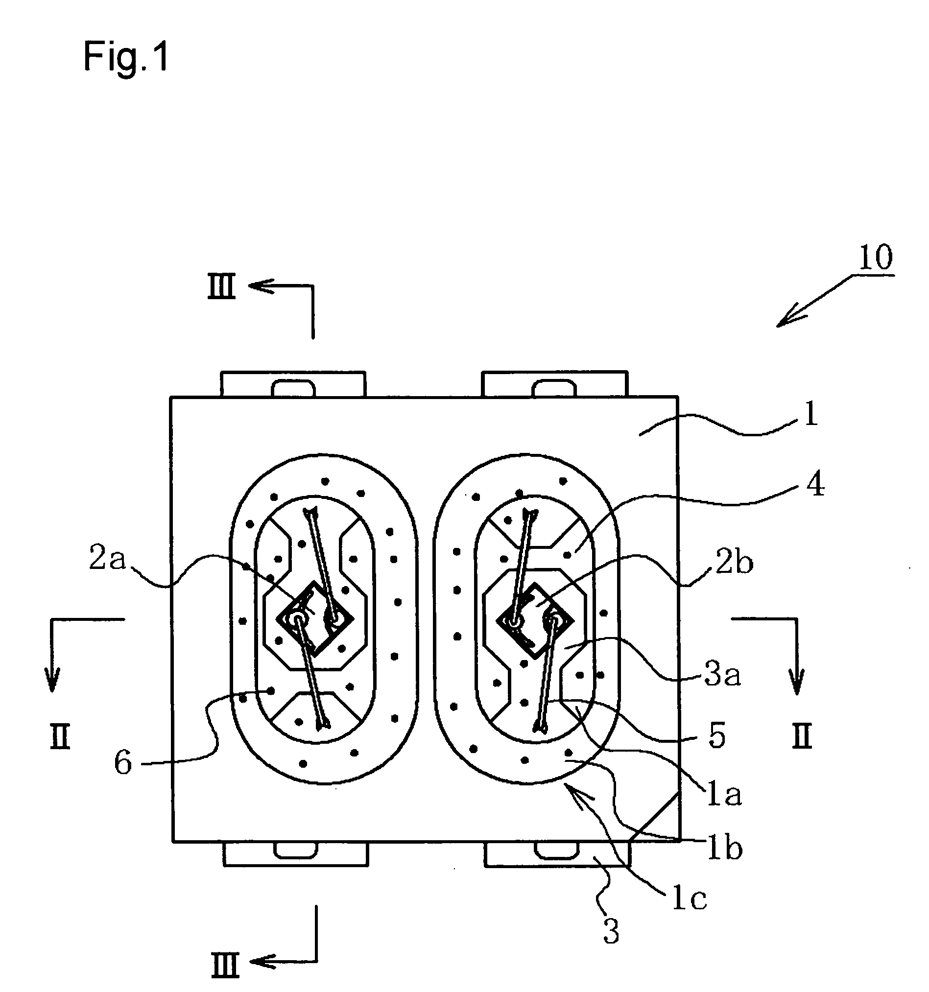
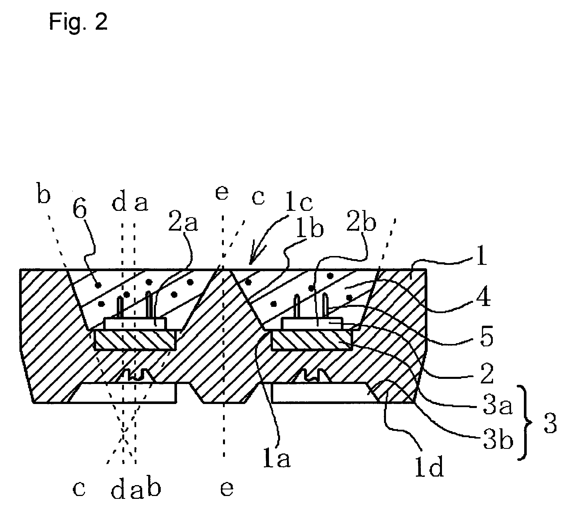
[0039]FIG. 1 is a plan view schematically showing the constitution of the light emitting apparatus of the first embodiment. FIG. 2 is a schematic sectional view taken along lines II-II of FIG. 1. FIG. 3 is a schematic sectional view taken along lines III-III of FIG. 1. FIG. 4 is a schematic perspective view showing the light emitting apparatus of the first embodiment on the back side thereof.

(Light Emitting Apparatus)

[0040] The light emitting apparatus 10 of the first embodiment comprises a light emitting device 2 and a package 1 that has two recesses 1c each having a bottom surface 1a where the light emitting device 2 is to be mounted and a side surface 1b extending from the bottom surface 1a. An electrode 3 is provided on the bottom surface 1a of the recess 1c of the package 1, with the light emitting device 2 mounted on a mount 3a of the electrode 3. The light emitting device 2 has a first light emitting device 2a and a second light emitting device 2b, while the first light em...

second embodiment

[0053]FIG. 5 is a schematic perspective view of a molded package according to a second embodiment. FIG. 6 is a schematic top view showing a state of the molded package according to the second embodiment where the light emitting device is mounted. FIG. 7 is a schematic sectional view along dashed line VII-VII of FIG. 6. FIG. 8 is a schematic rear view of the molded package according to the second embodiment.

[0054] The molded package 100 comprises a first base metal 101, a second base metal 102 and a third base metal 103 that are disposed to oppose each other and are isolated from each other by a molded member 105. The first base metal 101, the second base metal 102 and the third base metal 103 are formed by integral molding of the molded member 105, so that end portions thereof are inserted in the molded member 105 while the other end portions protrude from the outer wall surface of the molded member 105. The first base metal 101 protrudes from the outer wall surface that opposes th...

examples 1 and 2

[0110] The light emitting apparatuses of Examples 1 and 2 employ the constitution of the second embodiment. FIG. 5 is a schematic perspective view of the molded package according to the second embodiment. FIG. 6 is a schematic top view of the light emitting apparatus according to the second embodiment. FIG. 7 is a schematic sectional view of the molded package according to the second embodiment. FIG. 8 is a schematic rear view of the molded package according to the second embodiment. FIG. 9 shows an excitation spectrum of the nitride fluorescent material. FIG. 10 shows an emission spectrum of the nitride fluorescent material excited by a bluish purple LED of the light emitting apparatus according to the first embodiment. FIG. 11 shows an emission spectrum of the nitride fluorescent material excited by a bluish purple LED of the light emitting apparatus according to the second embodiment. FIG. 12 shows an emission spectrum of a green LED.

[0111] The first light emitting device 108a i...


PUM


Abstract

An object of the present invention is to provide a light emitting apparatus that allows it to easily control the driving of LED and has high color rendering properties.
The light emitting apparatus comprises the first light emitting device 108a that has first peak emission wavelength in blue region and emits blue light, the fluorescent material 140 that is excited by the light from the first light emitting device 108a and emits red light, the second light emitting device 108b that has second peak emission wavelength which is longer than the first peak emission wavelength and is shorter than peak emission wavelength of the fluorescent material 140, and the second light emitting device 108b that emits green light of second peak emission wavelength which is longer than the first peak emission wavelength, so as to emit light generated by blending of blue light, green light and red light to the outside.

Description

BACKGROUND OF THE INVENTION [0001] 1. Field of the Invention [0002] The present invention relates to a light emitting apparatus used as backlight source for liquid crystal, illumination apparatus, light source for computer display, flash light for camera, ancillary light source for movie picture or the like. [0003] 2. Description of the Related Art [0004] Cold cathode ray fluorescent tubes (CCFL) are currently used as the backlight source for the liquid crystal display of apparatuses other than mobile apparatus. However, it is strongly called for to replace the CCFL with light sources that do not use mercury, in order to avoid adverse effect on the environment. A light emitting apparatus that uses a light emitting device (hereinafter referred to as LED, too) receives much attention for that purpose. [0005] A light emitting apparatus using a light emitting device is compact, has high power efficiency and emits light with clear color. The light emitting device is a semiconductor devic...

Claims


Application Information

Patent Timeline
IPC IPC(8): H01J1/62H01L33/32H01L33/50H01L33/56H01L33/62
CPCC09K11/0883C09K11/7728H01L25/0753H01L33/50H01L33/60H05B33/14H01L2224/48465H01L2224/48247H01L2924/00
Inventor NAITOU, TAKAHIRO
Owner NICHIA CORP
Why Eureka
Try Eureka