Vibrator for bone-conduction hearing

a bone-conduction, vibrating technology, applied in the direction of mechanical energy handling, electrical transducers, transducer casings/cabinets/supports, etc., can solve the problem that the small magnets used in the vibrating device are very difficult to handle in the manufacturing process, and achieve the effect of improving durability and lowering the resonance frequency

Active Publication Date: 2006-03-02
OTICON
View PDF8 Cites 98 Cited by
  • Summary
  • Abstract
  • Description
  • Claims
  • Application Information

AI Technical Summary

Benefits of technology

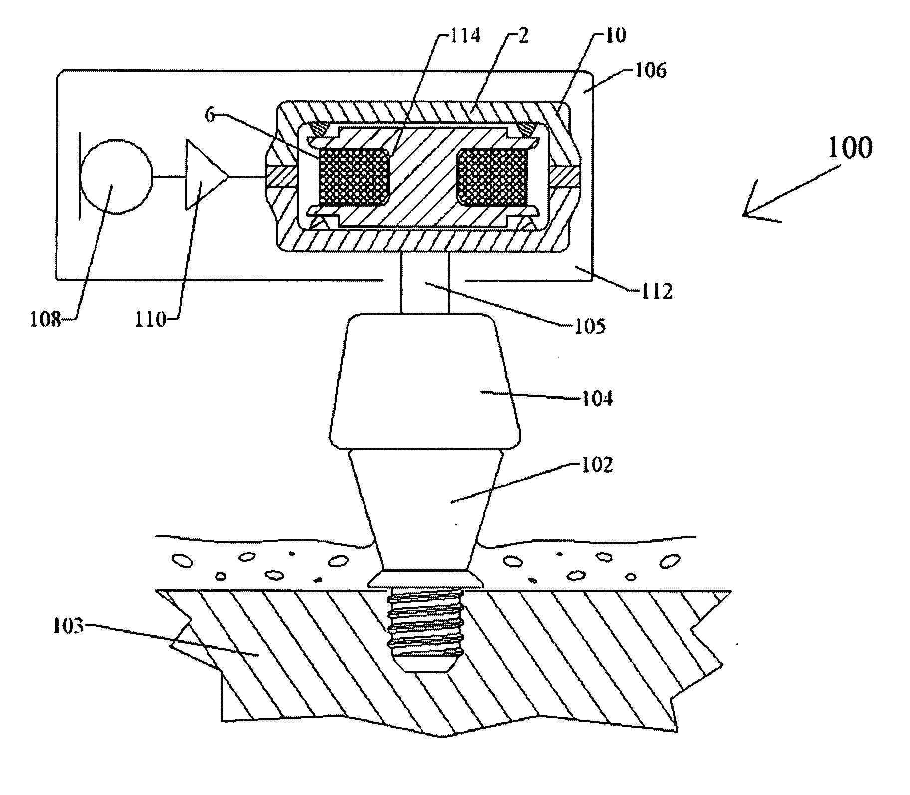
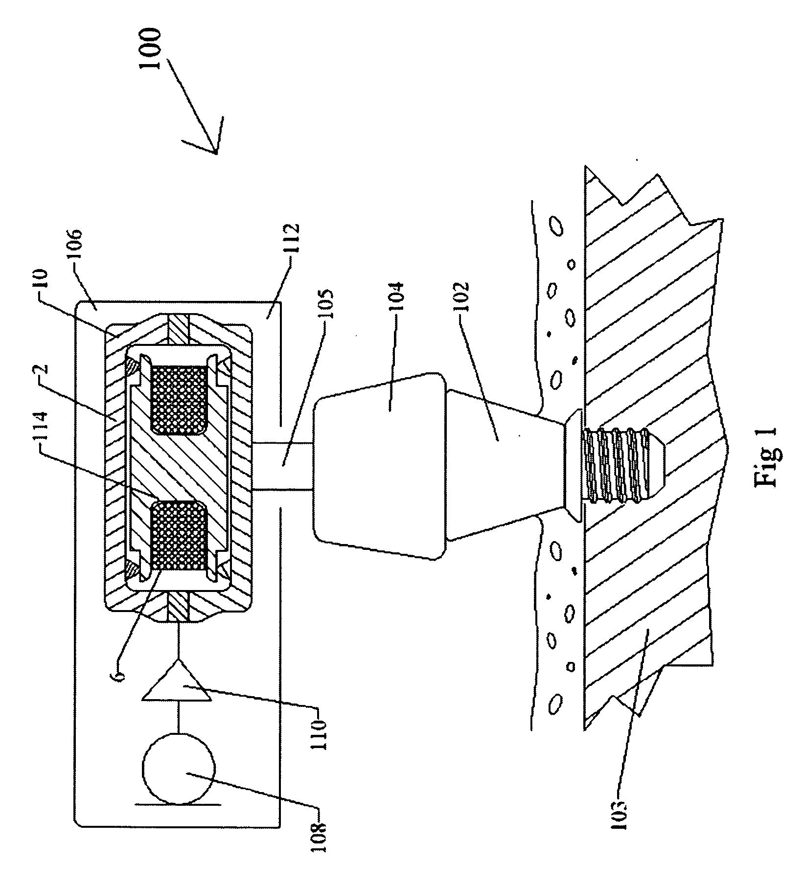
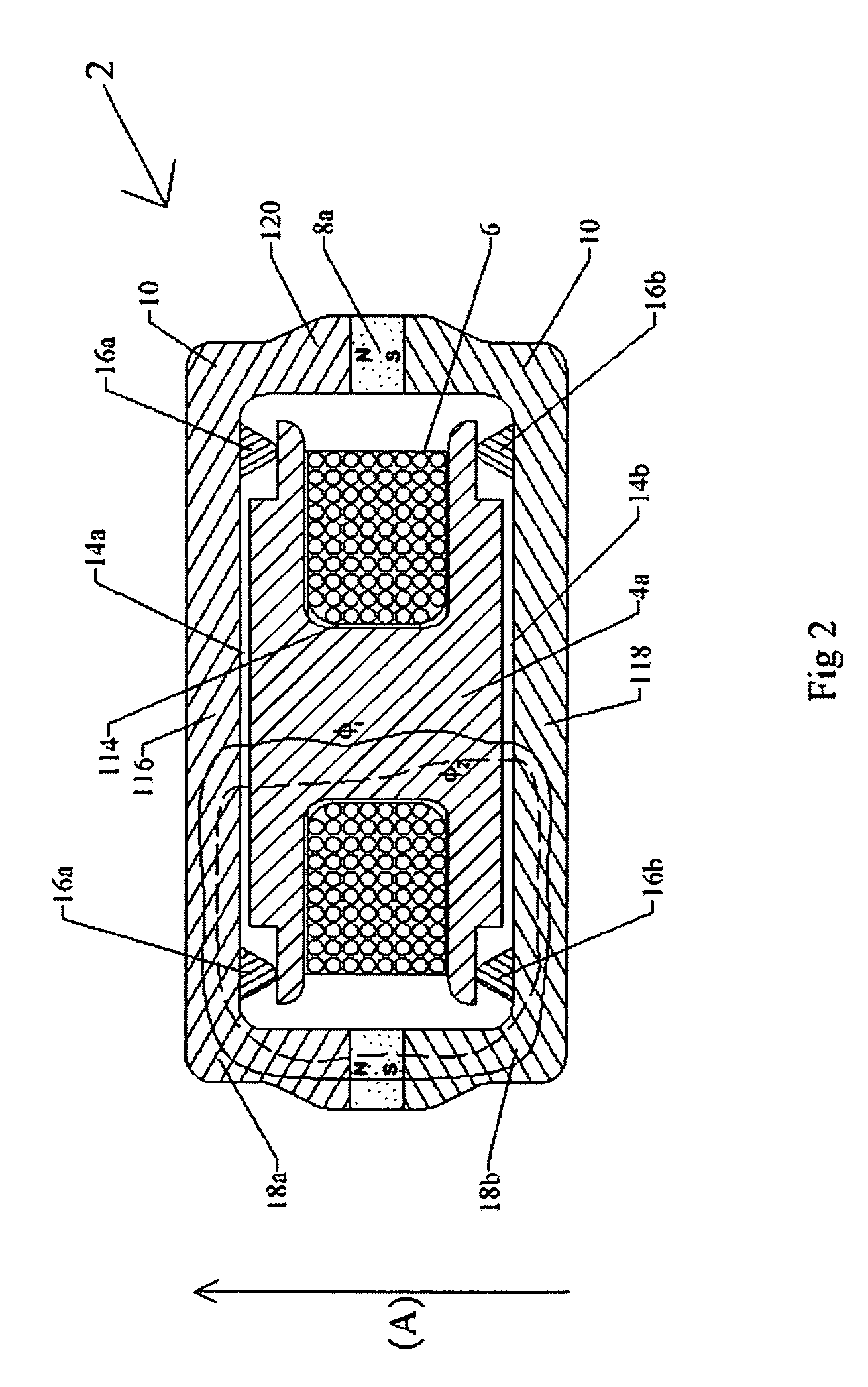
[0006] The vibrator of the present invention provides an effective solution to the above-outlined problems. The vibrator of the present invention has a balanced armature that makes it possible to use softer cushions / springs that can offer a lower resonance frequency without adding weight to the vibrator. The vibrator of the present invention has better durability compared to conventional vibrators because they exert a continuous load on the cushions or springs and require stiffer cushions.

Problems solved by technology

The small-sized magnets used in the vibrators are very difficult to handle in the manufacturing and the coils are sensitive and require wiring for its connection.

Method used


Image

  • Vibrator for bone-conduction hearing
  • Vibrator for bone-conduction hearing
  • Vibrator for bone-conduction hearing

Examples


second embodiment

[0030]FIG. 3 is a cross-sectional side view of a vibrator 122 that is similar the vibrator 2 of FIG. 2. The vibrator 122 has a coil 124 that is fixedly attached to an inner wall 126 of the housing 10 at the mid-section 120 thereof. In this way, the coil 124 does not vibrate as much as the bobbin 4a so that the wires to the coil are not subject to vibration to extend the durability of the wires and the coil.

third embodiment

[0031]FIG. 4 shows a preferred third embodiment of a vibrator 128 that has a permanent magnet 8b that is placed in a center of a bobbin 4b and inside the circular coil 6.

fourth embodiment

[0032]FIG. 5 is a cross-sectional side view of a preferred fourth embodiment of a vibrator 130 where the suspension of a bobbin 4c is carried out by two springs 22a, 22b that are placed outside a vibrator housing 132. The two springs 22a, 22b are secured to the housing with fixation screws 26a1, 26a2, 26b1, 26b2 and secured to the bobbin 4c in the fixation fittings 24a, 24b. The bobbin 4c is vibrating against the biasing forces of the springs 22a, 22b.


PUM


Abstract

The vibrator system is for generating bone conduction vibrations. A magnet (8a) provides a static magnetic flux (φ1) that follows a first path. A bobbin (4a) is disposed at a center a vibrator (2). A housing (10) encloses the bobbin and has a coil surrounding a center of the bobbin. The coil is powered by an alternating current for providing an alternating dynamic magnetic flux (φ2) following the first path through a magnetic circuit. The housing has an upper end (116). The upper end and the bobbin have a first gap (14a) formed therebetween. The housing has a lower end (118) opposite the upper end. The lower end and the bobbin have a second gap (14b) formed therebetween. The magnet is positioned so that the static magnetic flux (φ1) is passing through the first and second gaps in a direction substantially parallel with an axial direction (A) of the vibrator. Suspension means (16a, 16b) are provided for suspending the bobbin in a center of the housing.

Description

TECHNICAL FIELD [0001] The present invention relates to a vibrator for generating audio vibrations for providing bone-conduction hearing. BACKGROUND OF THE INVENTION [0002] Bone conduction is the principle of transmitting vibrations via the skull bone to the inner ear, i.e. the cochlea. Several different types of bone conduction hearing aids are available. The two most common types of such hearing aids are the traditional bone conductors and the direct bone conductors. The traditional bone conductor consists of a hearing aid with a vibrator that is pressed against the skull. The vibrations are then transmitted through the skin and the skull bone into the cochlea. The direct-bone conductors include an anchoring component that is attached to the skull bone and through which the vibrations are directly transmitted to the skull bone. [0003] All of such devices require a vibrator where the electrical signal is converted and transferred into mechanical vibrations. Preferably, electromagne...

Claims


Application Information

Patent Timeline
Patent Type & Authority Applications(United States)
IPC IPC(8): H02K7/06H02K7/10H04R25/00
CPCH02K33/18H04R25/606H04R11/02H04R9/025H04R9/066H04R2460/13
Inventor WESTERKULL, PATRIK
Owner OTICON
Why Eureka
Try Eureka