Electromagnetic wave transceiver apparatus and nuclear magnetic resonance analyzing apparatus using it

Inactive Publication Date: 2006-03-09
HITACHI LTD
View PDF0 Cites 6 Cited by
  • Summary
  • Abstract
  • Description
  • Claims
  • Application Information

AI Technical Summary

Benefits of technology

[0004] Further, in recent years, digital technologies have been introduced to the transmitter and receiver of the NMR apparatus. Especially, a digital technology in a low frequency range of about 10 MHz has been realized, making it possible to prepare and process a digital signal of an electromagnetic wave at several of tens of MHz to several of hundreds of MHz on a circuit board. Processing based on digital signals (hereinafter referred to as “digital processing”) is advantageous in that a signal delay due to a difference in wiring length on the board and a frequency or phase shift due to temperature-change dependent differences in characteristics of circuit constituent elements such as capacitors and inductors can be suppressed to assure more accurate measurement.
[0074] The NMR apparatus of the invention uses the electromagnetic transmitter incorporating a single DDS and therefore the production costs can be reduced to attain the effect of excellent packaging performance.

Problems solved by technology

In a NMR apparatus adopting the digital processing as above, however, the phase locked loop circuitry faces a problem that the circuit constant drifts and electrical noises take place suddenly under the influence of temperatures, making it difficult to keep the phase coincident over several hours between a circuitry for analog processing (hereinafter referred to as an “analog circuitry”) and a circuitry for digital processing (hereinafter referred to as a “digital circuitry”).
Recently, however, measuring time for measurement of protein with a NMR apparatus (hereinafter referred to as “NMR measurement”) tends to be prolonged and keeps continuing up to an extremity of several weeks.
Accordingly, measurement errors due to shifts in phase and amplitude during measurement cannot be suppressed sufficiently by the maintenance conducted at the aforementioned intervals.
Especially, coping with a phase shift attributable to a sudden electrical noise is very difficult to achieve.

Method used


Image

  • Electromagnetic wave transceiver apparatus and nuclear magnetic resonance analyzing apparatus using it
  • Electromagnetic wave transceiver apparatus and nuclear magnetic resonance analyzing apparatus using it
  • Electromagnetic wave transceiver apparatus and nuclear magnetic resonance analyzing apparatus using it

Examples


embodiment 1

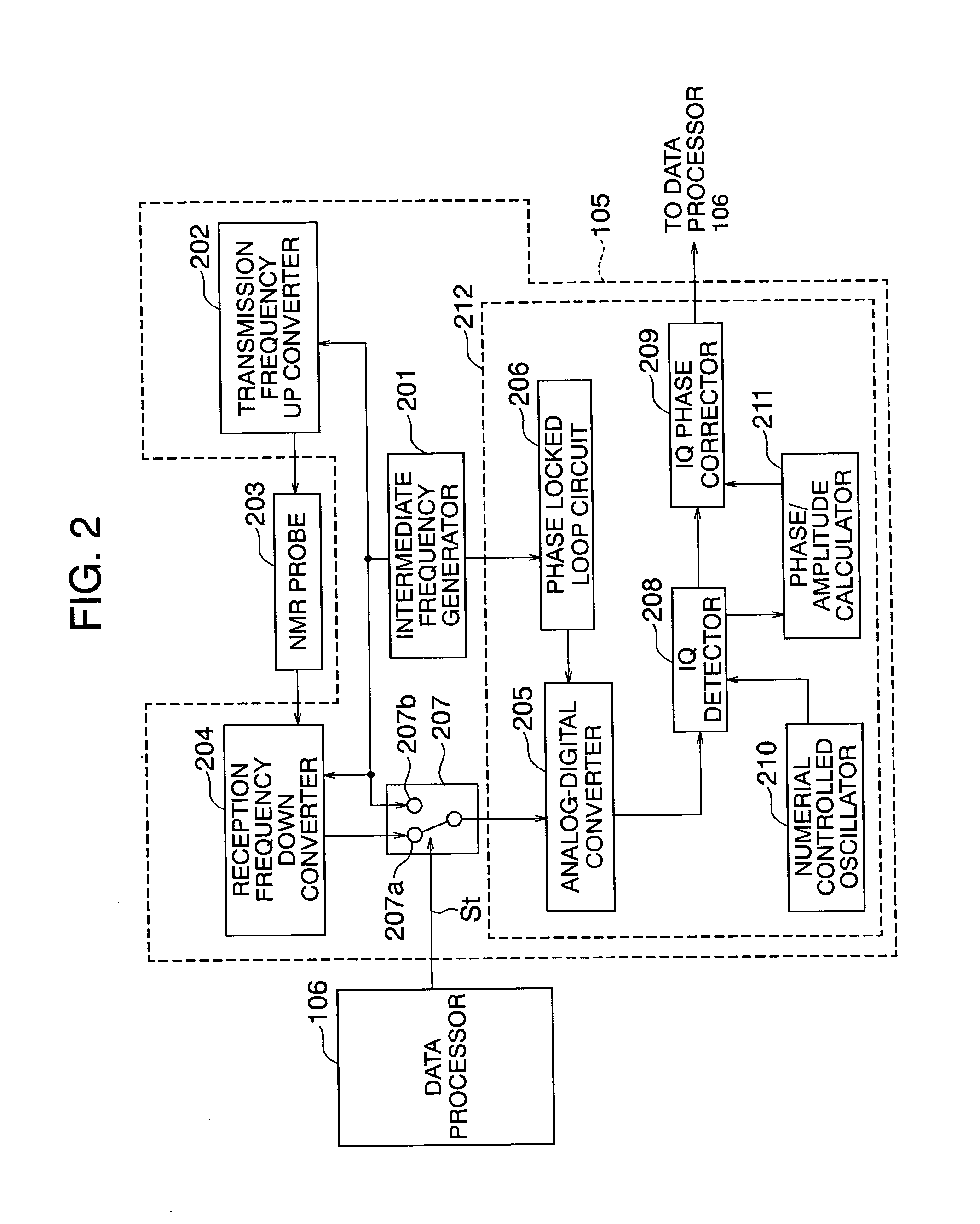
[0091] Making also reference to a block diagram of FIG. 2, the construction of NMR transceiver circuit 105, inclusive of peripheral components, according to a first embodiment of the invention will now be described. The NMR transceiver circuit according to the present embodiment includes an intermediate frequency generator 201 for generating an intermediate wave, a transmission frequency converter (for example, a frequency up converter) 202 for preparing, on the basis of an intermediate frequency of the intermediate wave prepared by the intermediate frequency generator, an electromagnetic wave to be transmitted to a sample, a reception frequency converter (for example, a frequency down converter) 204 for processing a free induction decay signal (hereinafter referred to as “FID signal”) a receiver coil in a NMR probe 203 has received as a result of transmission of the electromagnetic wave to the NMR probe 203, an analog-digital converter 205 (hereinafter referred to as “A / D converter...

embodiment 2

[0106] Turning now to FIG. 4, a second embodiment of the present invention will be described. The present embodiment is substantially the same as embodiment 1 with the only exception that switches are positioned differently and the construction of the remaining parts differs correspondingly.

[0107] In a NMR apparatus according to the present embodiment, a switch 207A is interposed between a transmission frequency up converter 202 and a NMR probe 203 and a switch 207B is interposed between a reception frequency down converter 204 and the NMR probe 203, so that the NMR probe can be on a roundabout route by providing a wiring line between these switches. The switches 207a and 207b can be controlled by timing commands sta and stb, respectively, from the data processor 106.

[0108] In the present embodiment, during the normal measurement, that is, when a FID signal is fetched from the NMR probe, the switches 207A and 207B responsive to the timing command sta and stb from the information p...

embodiment 3

[0113] Next, a NMR transceiver apparatus according to a third embodiment of the invention will be described.

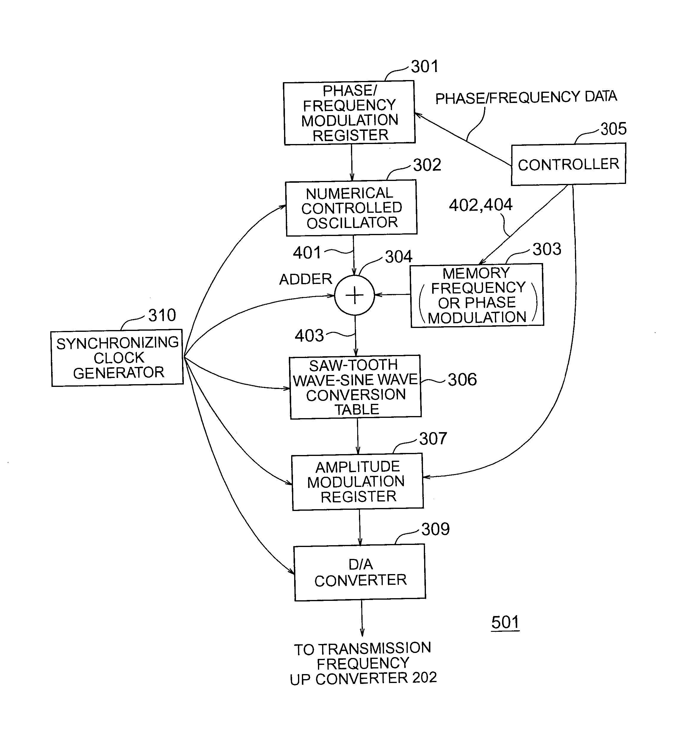
[0114] A NMR transceiver circuit according to the third embodiment of the invention is illustrated in block form in FIG. 5. The NMR transceiver circuit 105 includes a radio wave digital modulator 501 and a transmission frequency up converter 202 for preparing, on the basis of a modulation wave prepared by the radio wave digital modulator 501, an electromagnetic wave to be transmitted to a sample. The electromagnetic wave is applied to a transmitter coil of NMR probe 203 to generate a FID signal which in turn is received by a receiver coil of NMR probe 203 and processed by a reception frequency down converter 204. Further, the analog FID signal is converted into a digital FID signal by means of an A / D converter 205, to which a reference clock (or reference signal) generator 506 is connected. Also connected to the A / D converter 205 is an IQ detector 207 having its output transm...


PUM


Abstract

An electromagnetic transceiver apparatus for a NMR apparatus has an intermediate frequency generator for preparing an intermediate wave, a transmission frequency converter for preparing, on the basis of an intermediate frequency of the intermediate wave, an electromagnetic wave to be radiated from a transmitter coil, a reception frequency converter for processing a signal received by the NMR probe, an analog-digital converter for converting an output of the reception frequency converter into a digital signal, an IQ detector for performing detection on the basis of an output of the analog-digital converter, a phase locked loop and a switch inserted between the analog-digital converter and the reception frequency converter to select either an input from the intermediate frequency generator or an input from the reception frequency converter.

Description

BACKGOUND OF THE INVENTION [0001] The present invention relates to an electromagnetic wave transceiver apparatus and a nuclear magnetic resonance analyzing apparatus (hereinafter referred to as “NMR” apparatus) using it. [0002] In the NMR apparatus, an electromagnetic wave such as a radio wave or microwave having a period of about several nanoseconds is radiated to a sample placed in a static magnetic field and a free induction decay signal generated from the sample on the basis of or under the influence of the electromagnetic wave is received to analyze the sample. Recently, the NMR apparatus has been expected to be used especially for specifying composition and structure of, for example, protein. [0003] Generally, the NMR apparatus has a magnet unit for generating a static magnetic field, a transmitter coil arranged around a sample to radiate an electromagnetic wave to the sample, a transmitter for generating and transmitting the electromagnetic wave to be radiated from the transm...

Claims


Application Information

Patent Timeline
IPC IPC(8): G01B7/14
CPCG01R33/3621G01R33/3607
Inventor HABARA, HIDETAPARK, MINSEOK
Owner HITACHI LTD
Why Eureka
Try Eureka