Method for producing an electrochromic device and said electrochromic device

a technology of electrochromic devices and electrochromic devices, which is applied in the direction of optics, instruments, chemistry apparatuses and processes, etc., can solve the problems of limiting the workability of the device as a whole, unserviceable devices, and insufficient light attenuation efficiency of the prepared electrochromic devices, etc., to achieve higher stability, longer persistence of colouring and bleaching uniformity, and high stability of the electrochromic devices

Inactive Publication Date: 2006-03-09
AVELUM +1
View PDF1 Cites 24 Cited by
  • Summary
  • Abstract
  • Description
  • Claims
  • Application Information

AI Technical Summary

Benefits of technology

[0006] It is an object of the present invention to provide an electrochromic device, having an electrochromic composition in the form of a polymer layer, in particular, a solid-like one, exhibiting no volume shrinkage during structuring over a broad temperature range and ensuring a higher stability of the electrochromic device operating under long-term maintenance of the coloured state and under high control voltages and changing of the electrode polarity. The higher stability implies a longer persistence of the colouring and bleaching uniformity, especially for an electrochromic device with a large work surface area.

Problems solved by technology

Thus, the proper electrochromic composition is prepared only after completion of the assembling the said electrochromic device, that restricts the workability of the device as a whole.
Since polyoxometallate is an inorganic electrochromic component and, therefore, it has a lower extinction coefficient than organic electrochromic components, thus prepared electrochromic device does not ensure a sufficient efficiency of light attenuation without a substantial energy consumption.
This adverse effect is mainly typical for electrochromic devices having a large work surface area of optically transparent SnO2:F-electrodes.
Besides, in the process of producing the electrochromic device, after dissolution of the polymer and clarification of the electrochromic composition, air bubbles appear over the whole work surface of the device, which makes the device unserviceable.
However, polymerization reactions are accompanied by volume shrinkage, which has an adverse effect on the quality of the electrochromic device.
The adverse effect can become apparent especially in electrochromic devices with relatively large inter-electrode gaps (1-2 mm), which are usually provided in electrochromic devices with large work surfaces (more than 0.5 m2).

Method used


Image

  • Method for producing an electrochromic device and said electrochromic device
  • Method for producing an electrochromic device and said electrochromic device

Examples


example 1

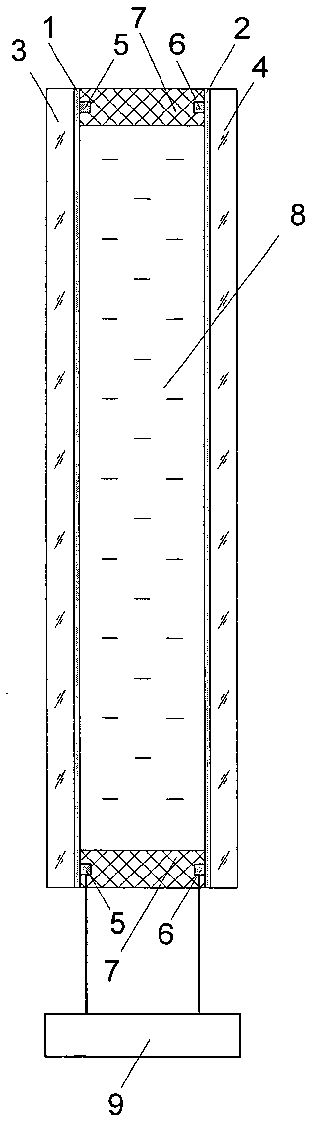
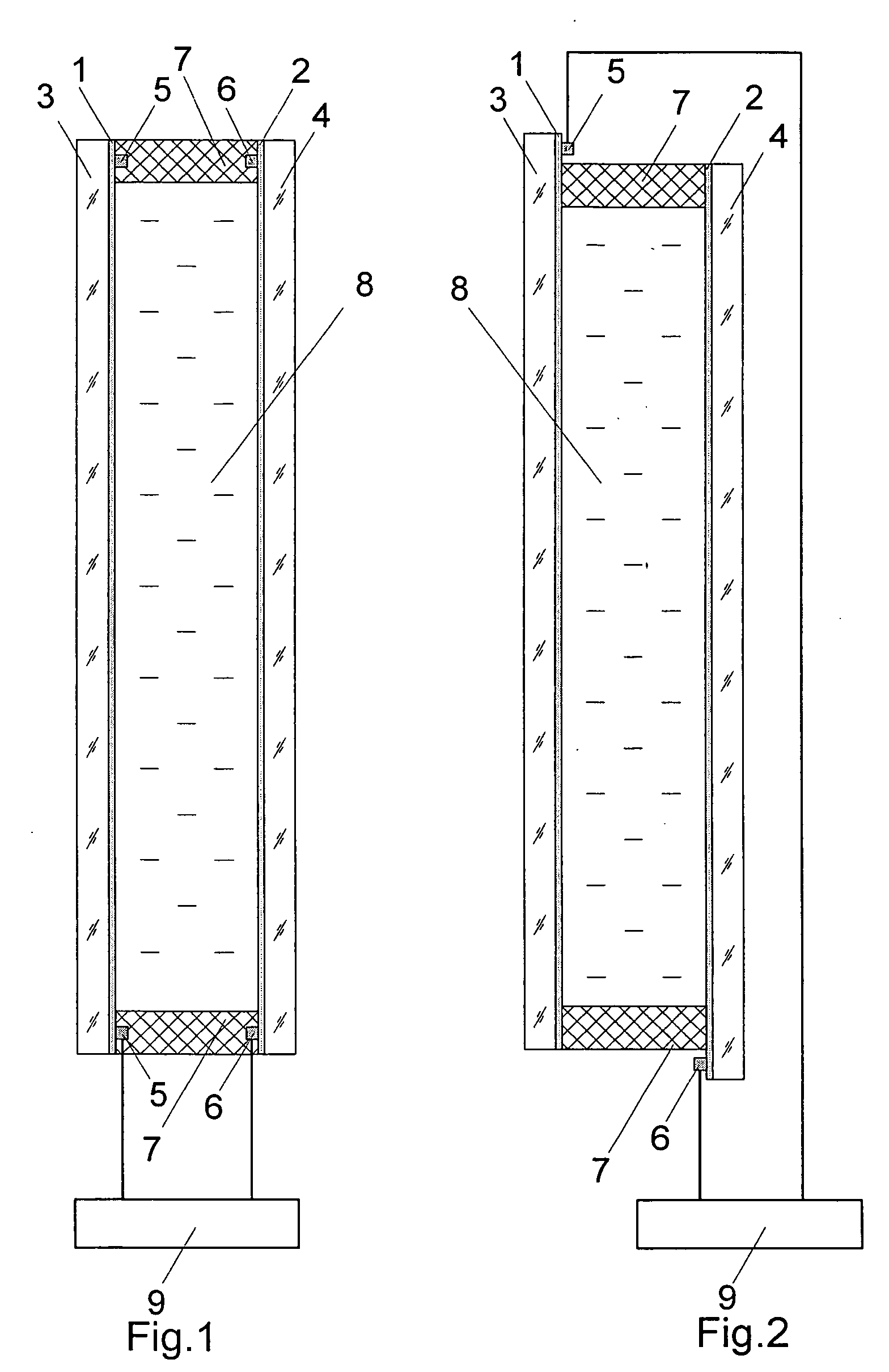
[0050] An electrochromic device comprising two optically transparent SnO2 electrodes with a surface electrical resistance of 18 ohm / m2 and a glass substrate thickness of 4 mm (K-glass, produced by Pilkington) was produced. The electrode dimensions were 20×30 cm2. The electrodes were shifted with respect to each other to ensure the current input along the longer side and were bonded along the perimeter by an epoxide-based adhesive containing spacers to form an inter-electrode gap of 0.4 mm. In the 5-mm wide glue line, an opening was left for filling the device with the initial electrochromic composition representing a disperse system in the form of a suspension, comprising the following components: a dispersion medium (electrochromic solution)—a solution of 0.01M 1,1′-dimethyl-4,4′-dipyridinium diperchlorate and 0.01M ferrocene in γ-butyrolactone; a disperse phase (20.7% wt)—the Vitan-2M copolymer. Prior to preparing the suspension, the electrochromic solution was cooled down to abou...

example 2

[0052] The electrochromic device was produced as in Example 1 except that the initial electrochromic composition was evacuated for 12 min before filling.

[0053] On the expiry of about 1.5 h at a temperature of 20° C., the uniformly dim initial electrochromic composition became transparent without emerging any visible air bubbles and without volume shrinkage. The light transmission of the device in the visible spectral region was 78%. On application of a direct voltage of 1.5 V to the device, the electrochromic layer acquired a uniformly blue colour over the window area, while upon short-circuiting of the electrodes, the light transmission of the device returned to the initial value. After unsealing of the device, the electrochromic composition was a solid-like film.

example 3

[0054] Two electrochromic devices with dimensions 50×100 cm2, each comprising two optically transparent SnO2-electrodes with a surface electric resistance of 18 ohm / m2 and a glass substrate thickness of 4 mm (K-glass) were produced. The electrodes were bonded together along the perimeter by the two-sided adhesive tape VHB 4910 with a thickness of 1 mm and a width of 6 mm with two openings for filling the device with the electrochromic disperse system. Along the longer side of each electrode, feed wires (copper conductors 0.2 mm in diameter) were laid under the adhesive tape and brought outside. The inner space of device No. 1 thus formed was filled, by injection, with the initial electrochromic composition representing a disperse system in the form of a suspension, comprising the following components: a dispersion medium (electrochromic solution)—a solution of 0.01M 1,1′-dimethyl-4,4′-dipyridinium diperchlorate and 0.01M ferrocene in a γ-butyrolactone (60% vol.)—propylene carbonate ...


PUM

PropertyMeasurementUnit
particle sizeaaaaaaaaaa
temperatureaaaaaaaaaa
thicknessaaaaaaaaaa

Abstract

The invention relates to a method for producing electrochromic devices, in particular that having a large working surface area and which does not produce a volumetric shrinkage and can operate during a long maintenance of electrocoloured state of an electrochromic compound, high control voltages and polarity inversion. The inventive electrochromic device comprises at least two electrodes (1, 2), at least one of them being optically transparent. A closed sealed space is formed between said electrodes and filled with the electrochromic compound which is embodied in the form of a solid-like film. The inventive method for producing the electrochromic device consists in prefabricating an initial electrochromic compound in the form of a dispersed electrochromic system which contains at least a suspension and/or colloid. The dispersed medium of said system is embodied in the form of an electrochromic solution containing a liquid solvent, cathode and anode components, a disperse phase being embodied in the form of a finely dispersed polymer. Afterwards, the initial electrochromic compound is deaerated, thereby eliminating dissolved oxygen and air introduced by said finely dispersed polymer, and is used for filling the space between the electrodes.

Description

TECHNICAL FIELD [0001] The present invention relates to devices ensuring colour change (colouring or bleaching) under the action of electric current, namely, to electrochromic devices and the technology for their manufacture. Electrochromic devices have an electrically controlled light absorption or reflection. These devices include anti-glare rear-view mirrors in automobiles, light ports, dimming visors, smart windows, multiple-access display boards, etc. BACKGROUND OF THE INVENTION [0002] A method is known for producing an electrochromic device (U.S. Pat. No. 4,902,108, 20.02.1990), wherein a thickened solution of polymethyl methacrylate in a low-boiling solvent is applied onto a conducting layer of one of two optically transparent electrodes, then the solvent is evaporated to give a polymethyl methacrylate layer. Thereafter the optically transparent electrodes are glued together along the perimeter at a specified distance from each other and a closed space between them is filled,...

Claims


Application Information

Patent Timeline
Patent Type & Authority Applications(United States)
IPC IPC(8): G02F1/15C09K9/02G02F1/1503G02F1/161
CPCC09K9/02C09K2211/1044C09K2211/187G02F2001/1512G02F1/161G02F2001/151G02F1/1521G02F2001/1518G02F1/1503G02F2001/15145
Inventor GAVRILOV, VLADIMIR IVANOVICHSHELEPIN, IGOR VICTOROVICH
Owner AVELUM
Why Eureka
Try Eureka