Method for determining the signal-to-noise ratio of an optical signal

a signal-to-noise ratio and optical signal technology, applied in the direction of transmission monitoring, transmission monitoring/testing/fault-measurement systems, electrical equipment, etc., can solve the problems of limited transmission range of multichannel wdm signal that can be spanned using wave division multiplex (wdm) transmission systems, channel spacing, and number of wavelength channels

Inactive Publication Date: 2006-03-09
SIEMENS AG
View PDF7 Cites 17 Cited by
  • Summary
  • Abstract
  • Description
  • Claims
  • Application Information

AI Technical Summary

Benefits of technology

[0016] A further advantage of the invention is that it is not necessary to set a particular polarization state selectively, so that no complex adjustment is necessary.
[0017] As measurements are performed for any polarization states, a plurality of measurement points for all the channels is simultaneously obtained for a given setting of the two plates, so that the measurement time is independent of the number of channels.
[0018] Advantageous developments of the invention are set out in the sub-claims.

Problems solved by technology

The multichannel WDM signal transmission range that can be spanned using wave division multiplex (WDM) transmission systems is limited, among other things, by the amplified spontaneous emission (ASE) produced in optical amplifiers as noise power which is superimposed on the optical signals in the channels.
Because of the substantial increase in the number of wavelength channels and the accompanying reduction in channel spacing, this method can no longer be used.
In addition, the components used for influencing the spectrum and for coupling signals in and out in modern transmission systems within the route preclude the use of this method.
However, the main disadvantage of all hitherto known proposals for implementing this method is that each channel has to be individually selected by spectral filtering and a defined polarization state for optimum suppression of the polarized signal portion must be set using a polarization controller.
This method is therefore very complex / costly and results in long measurement times. The two following articles describe the basic principles of the method: “OSNR Monitoring Technique Based on Polarisation Nulling Method”, J. H. Lee, D. K. Jung, C. H. Kim, Y. C. Chung, WEEE Photonics Technology Letters, Vol. 13, No. 1, January 2001; “Improved OSNR Monitoring Technique Based on Polarisation Nulling Method”, J. H. Lee, Y. C. Chung, Electronics Letters, 19th Jul. 2001, Vol. 37, No. 15.
Also with this method the equipment complexity is high due to the necessary computing and evaluation unit combined with the filter unit.
One disadvantage of this method is the large amount of time required for measuring a very large number of WDM channels, as all the channels have to be sequentially measured independently as described above.
A major disadvantage is that a particular polarization state must first be set at the polarizer input.
As a control system for 360° rotation of the polarizer is necessary for measuring the signal-to-noise ratios or to achieve one or two required polarization states, this method exhibits a disadvantageous measurement redundancy, making it a time-consuming process.
In practice it is of course impossible to cover all polarization states.

Method used


Image

  • Method for determining the signal-to-noise ratio of an optical signal
  • Method for determining the signal-to-noise ratio of an optical signal
  • Method for determining the signal-to-noise ratio of an optical signal

Examples


Embodiment Construction

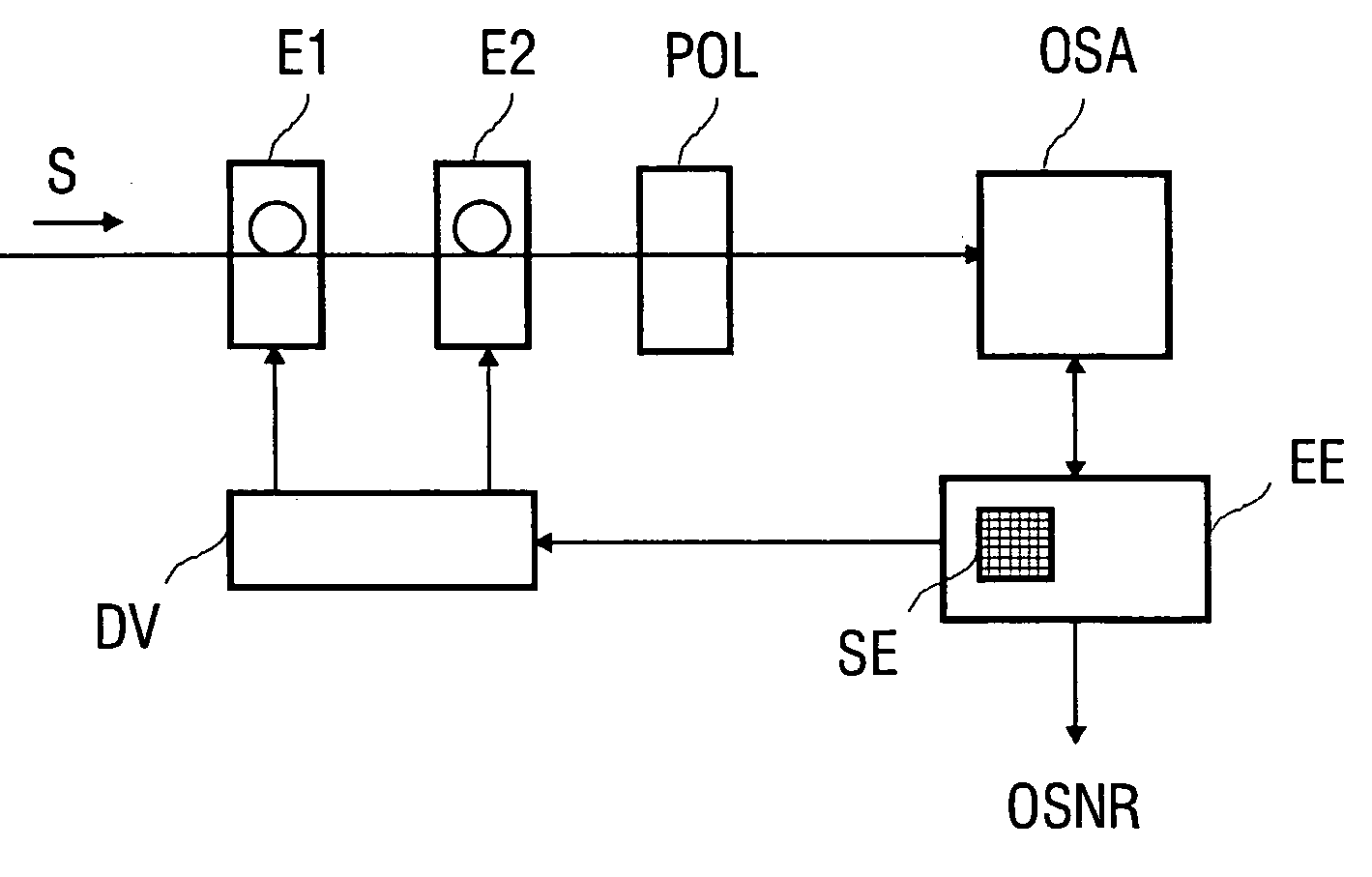
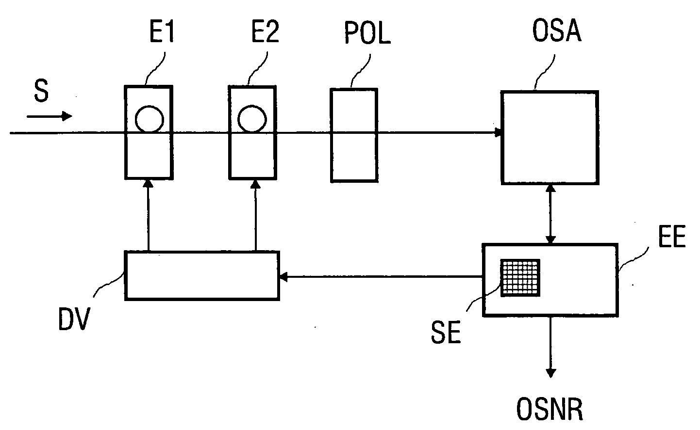
[0021] To provide a simpler illustration of the method according to the invention, a device according to FIG. 1 is selected in such a way that a WDM signal S is first fed to a polarization controller PS comprising a λ / 4 plate E1 and a λ / 2 plate E2 as phase retarder plates. The polarization controller PS is followed by a polarizer POL. For different settings of the polarizer or of the polarization state allowed through from the polarization controller, the spectral power density at the output of this device is recorded in each case by means of an optical spectrum analyzer OSA. The optical spectrum analyzer OSA can be preceded by a wavelength demultiplexer or a wavelength-selective filter, so that selected channels or only one channel of the WDM signal can be recorded. However, demultiplexing is in practice unnecessary. Connected to the optical spectrum analyzer OSA is an optical signal-to-noise ratio (OSNR) determination unit EE in which an interpolation and a deviation search of the...


PUM


Abstract

A method for determining signal-to-noise ratios and noise levels in an optical signal is disclosed, the first polarisation state of which is converted into a second polarisation state by means of number of tunings of a polarisation regulator. Defined changes to the second polarisation state are adjusted on the Poincare sphere by means of the polarisation regulator, whereby power values for the optical signal are determined after selection of a component of the electrical field. Some of the determined power values for the optical signal are stored and serve for the calculation of the signal-to-noise ratio of optical signals. Said method is rapid, requires little complicated equipment and is particularly suitable for a WDM transmission system in which many channels in a WDM signal are transmitted with small channel separations.

Description

CROSS REFERENCE TO RELATED APPLICATION [0001] This application is the US National Stage of International Application No. PCT / DE2003 / 002671, filed Aug. 8, 2003 and claims the benefit thereof. The International Application claims the benefits of German Patent application No. 10239305.2 DE filed Aug. 27, 2002, both of the applications are incorporated by reference herein in their entirety.FIELD OF THE INVENTION [0002] The invention relates to a method and a device for determining the signal-to-noise ratio (OSNR) of an optical signal according to the preambles of the claims. BACKGROUND OF THE INVENTION [0003] The multichannel WDM signal transmission range that can be spanned using wave division multiplex (WDM) transmission systems is limited, among other things, by the amplified spontaneous emission (ASE) produced in optical amplifiers as noise power which is superimposed on the optical signals in the channels. This noise power must be measured for optimum adjustment of the transmission...

Claims


Application Information

Patent Timeline
Patent Type & Authority Applications(United States)
IPC IPC(8): H04B10/08H04B10/00H04B10/02H04B10/079
CPCH04B10/07953
Inventor MARTIN, JURGENRAPP, LUTZ
Owner SIEMENS AG
Why Eureka
Try Eureka