Nanobubble utilization method and device

a technology of nanobubbles and nanobubbles, which is applied in the direction of vibration massage, disinfection, cleaning using liquids, etc., can solve the problems of real problem of considering the effective utilization of the above-described nanobubbles, and achieve the effect of large surface area per volume and improved function of the nanobubbles

Inactive Publication Date: 2006-03-16
NAT INST OF ADVANCED IND SCI & TECH
View PDF8 Cites 155 Cited by
  • Summary
  • Abstract
  • Description
  • Claims
  • Application Information

AI Technical Summary

Benefits of technology

[0023] Therefore, an object of the present invention is to provide a nanobubble-utilizing method and apparatus for effectively utilizing nanobubbles of which existence was clarified and generation apparatus was established by the inventors of the present application.
[0024] The inventors of the present application elucidated the characteristics of the above-described nanobubbles and found the following matters. That is, the nanobubble with a diameter of about 50 nm to 100 nm has a pressure of about several tens atms due to the surface tension within water and can generate an air jet when the bubble collapses, whereby the cleaning effect for the surfaces of an object can be expected. Also, since the surface activity of the bubble is high and foil components can be adsorbed to the interface, the foul component of water can be effectively removed. In particular, the bubble of an about 100 nm diameter has a surface area about several ten thousands times as large as that of a bubble of about several mm diameter usually observed for the same volume, and the bubble of an about 100 nm diameter is expected to have a high cleaning speed. Also, according to the calculation result of the molecular dynamics for air bubbles having a nanometer order size within the water, it is expected that the hydrogen bonds of the water interact with one another and the probability where hydrogen atoms exist within the bubble is large. Thus, it was proved that when such mutual action of molecules is exerted, the charge separation similar to soap can be realized at the air-liquid interface due to the bubbles having a nanometer-order size, whereby the cleaning promotion effects and the electrostatic sterilizing effects can be expected.
[0026] As another embodiment in which the cleaning method and apparatus utilizing nanobubbles according to the present invention are realized more concretely, there is one in which nanotechnology-associated equipments are cleaned by the ultra-pure water at the time of cleaning objects by the water comprising nanobubbles. Also, industrial equipments are cleaned by the water comprising nanobubbles and an organism is cleaned by the water comprising nanobubbles. The water to be used is electrolyzed water, ionized alkaline water or acid water. When the microbubbles are imparted to the water comprising nanobubbles, the function of the nanobubbles can be further improved.
[0027] Also, since the surface activity of the bubbles is high in the nanobubbles as described above, foul components can be absorbed to the interface, so that the nanobubbles are effective for removing foul components in water. Also, still another embodiment of the method and apparatus for utilizing the nanobubbles according to the present invention is arranged to utilize the nanobubbles so as to absorb polluted material by utilizing such characteristics that the nanobubbles have a quite large surface area per volume. Also, microbubbles are mixed to the water so that the nanobubbles having absorbed the polluted material in this manner move upward within the water.

Problems solved by technology

Thus, it became a real problem to consider the effective utilization of the above-described nanobubbles.

Method used


Image

  • Nanobubble utilization method and device
  • Nanobubble utilization method and device
  • Nanobubble utilization method and device

Examples


Embodiment Construction

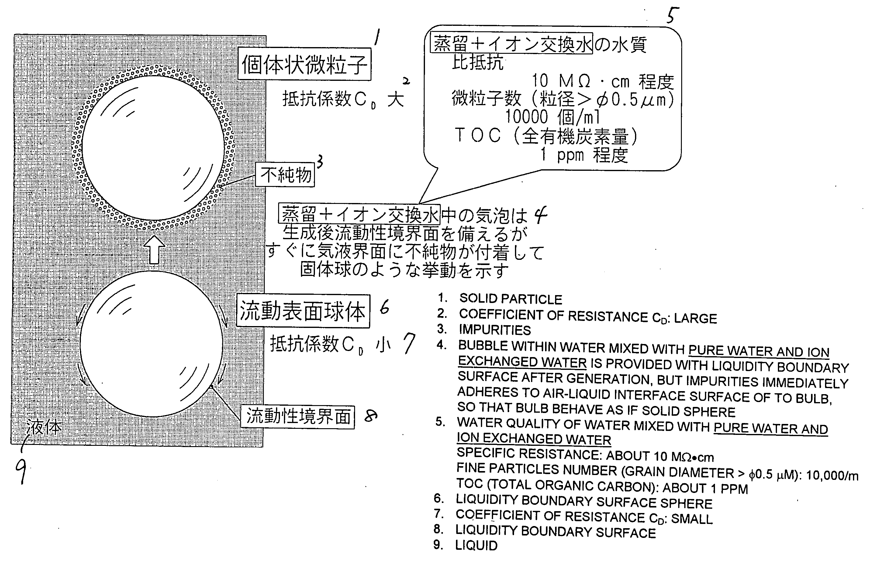
[0038] As has been already disclosed in the above-described patent application, the inventors of the present application clarified the technique for surely generating the nanobubbles by the electrolysis or the application of an ultrasonic wave. Thus, the inventors of the present application have thought how to effectively utilize the nanobubbles and elucidated the characteristics of the nanobubbles, the results of which is shown in FIG. 1.

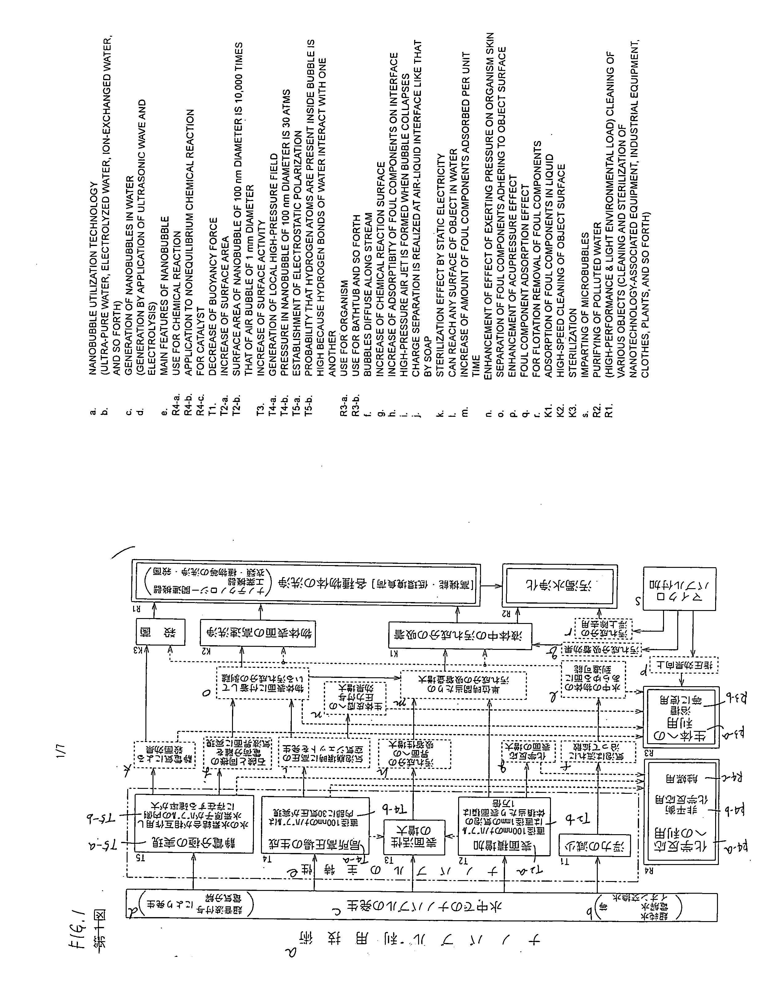
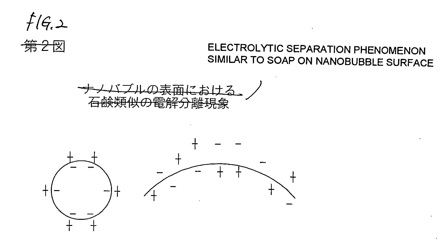
[0039] As is clear from FIG. 1, the nanobubbles can be generated by the application of an ultrasonic wave or the electrolysis in not only normal water but also ultra-pure water, electrolyzed water, or alkaline water or acid water using ion-exchanged water. The nanobubbles thus generated have major characteristics shown by T1 to T5 in the figure.

[0040] As is shown in FIG. 1, the nanobubble has a particularly remarkable characteristics in increase of the surface area (T2). In this respect, according to the conventional investigation in the microbub...


PUM

PropertyMeasurementUnit
diameteraaaaaaaaaa
diameteraaaaaaaaaa
heightaaaaaaaaaa

Abstract

The present inventors have found the presence of a nanobubble that has not been confirmed conventionally, and established a method for producing nanobubbles. The inventors have determined the theoretically expected characteristics of the produced nanobubbles, found new characteristics by analyzing data experimentally collected, and elucidated the relationship among the characters. Specifically, the inventors have found that a nanobubble has features such as decrease of the buoyant force, increase of the surface area, increase of the surface activity, generation of a local high-pressure field, interface activating action, and sterilizing action thanks to electrostatic polarization. By the association among the features, any of wide variety of objects can be cleaned with high performance and with light environmental load thanks to the function of adsorbing foul components, the function of cleaning the surface of an object quickly, and the sterilizing function, and polluted water can be purified. Nanobubbles can be applied to an organism to recover from fatigue and effectively used for chemical reactions.

Description

TECHNICAL FIELD [0001] The present invention relates to a nanobubble-utilizing method and apparatus for effectively utilizing nanobubbles in various fields by utilizing characteristics of bubbles having a diameter of nanometer-order, such as increase of surface areas, generation of a high pressure, realization of electrostatic polarization, increase of surface activity, and decrease of a buoyant force. BACKGROUND ART [0002] Conventionally, various investigations have been made as to microbubbles having a diameter of micrometer-order. That is, bubbles having a diameter of about 10 microns are generated by cavitation. Then, it have been considered and partially used that the microbubbles are used for environment protection by utilizing the function of the microbubbles such as air-liquid dissolution and floatation or by utilizing the function of cleaning water polluted by oil and the like, or are used for promoting the growth of water-borne animals and plants by utilizing the growth pr...

Claims


Application Information

Patent Timeline
Patent Type & Authority Applications(United States)
IPC IPC(8): B08B3/12B08B6/00A01K61/00A01G31/00A01K63/04A61H23/00A61H33/02A61L2/02A61L9/012B08B3/08B08B3/10C02F1/24C02F1/34
CPCA61L2/02A61L9/012C02F2303/04B82Y30/00C02F1/24B08B3/10Y02P60/60
Inventor YABE, AKIRAGOTO, MIZUKI
Owner NAT INST OF ADVANCED IND SCI & TECH
Why Eureka
Try Eureka