Methods for manipulating droplets by electrowetting-based techniques

a droplet and electrowetting technology, applied in the field of droplet-based liquid handling and processing, can solve the problems of high mixing difficulty, crosstalk or contamination between sensors, and affecting chip design and system flow rate, etc., and achieves high throughput capability, improved controllability, and high mixing accuracy.

Inactive Publication Date: 2006-03-16
DUKE UNIV
View PDF15 Cites 244 Cited by
  • Summary
  • Abstract
  • Description
  • Claims
  • Application Information

AI Technical Summary

Benefits of technology

[0016] The partitioning of liquids into discrete, independently controlled packets or droplets for microscopic manipulation provides several important advantages over continuous-flow systems. For instance, the reduction of fluid manipulation, or fluidics, to a set of basic, repeatable operations (for example, moving one unit of liquid one unit step) allows a hierarchical and cell-based design approach that is analogous to digital electronics.
[0017] In addition to the advantages identified hereinabove, the present invention utilizes electrowetting as the mechanism for droplet actuation or manipulation for the following additional advantages:
[0021] 4. Mixing-ratio control using programming operations, yielding better controllability and higher accuracy in mixing ratios.
[0023] 6. Enabling of integration with optical detection that can provide further enhancement on asynchronous controllability and accuracy.
[0029] According to one embodiment of the present invention, an apparatus for manipulating droplets comprises a substrate comprising a substrate surface, an array of electrodes disposed on the substrate surface, an array of reference elements, a dielectric layer disposed on the substrate surface, and an electrode selector. The reference elements are settable to a reference potential. The array of reference elements is disposed of in substantially co-planar relation to the electrode array, such that each reference element is adjacent to at least one of the electrodes. The dielectric layer is disposed on the substrate surface and is patterned to cover the electrodes. The electrode selector can be provided as a microprocessor or other suitable component for sequentially activating and de-activating one or more selected electrodes of the array to sequentially bias the selected electrodes to an actuation voltage. The sequencing performed by the electrode selector enables a droplet disposed on the substrate surface to move along a desired path that is defined by the selected electrodes.
[0044] It is yet another object of the present invention to provide an architecture suitable for efficiently performing binary mixing of droplets to obtain desired mixing ratios with a high degree of accuracy.

Problems solved by technology

Because the sensors lie in a common channel, crosstalk or contamination between sensors is often a concern.
Additionally, mixing in microfluidic flows is usually quite challenging.
Sufficient time and distance must be provided for mixing, which places constraints on chip design and system flow rates.
A common limitation among all continuous-flow systems is that fluid transport is physically confined to permanently etched structures, and additional mechanisms are required to enhance mixing.
This in turn requires the use of valves and complex channeling, consuming valuable real estate on a chip.
In the microscopic world, effective mixing is a technical problem because it is difficult to generate turbulent flow by mechanical actuation.
Thus, mixing that depends on diffusion through limited interfacial areas is a limitation.
This causes chaotic rearrangement of fluid particles, and thus the mixing two liquids.
One disadvantage of purely diffusion-based static mixing is the requirement of a complex 3D structure in order to provide out-of-plane fluid flow.
Another disadvantage is the low Reynolds number characterizing the flow, which results in a long mixing time.
A problem for active mixers is that energy absorption during the mixing process makes them inapplicable to temperature-sensitive fluids.
Thus, liquids with low conductivity could not be properly mixed.
When the perturbation force comes from a mechanical micropump, however, the presence of the valveless micropump makes the control of flow ratios of solutions for mixing quite complex.
In continuous flow systems, the control of the mixing ratio is always a technical problem.
However, the dependence of pressure on the properties of the fluid and the geometry of the mixing chamber / channels makes the control very complicated.

Method used


Image

  • Methods for manipulating droplets by electrowetting-based techniques
  • Methods for manipulating droplets by electrowetting-based techniques
  • Methods for manipulating droplets by electrowetting-based techniques

Examples


example

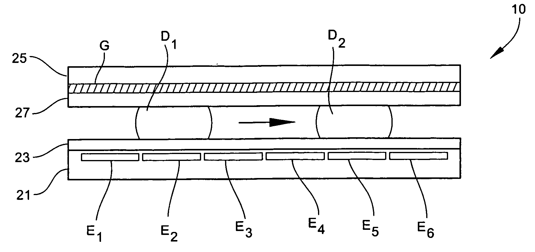
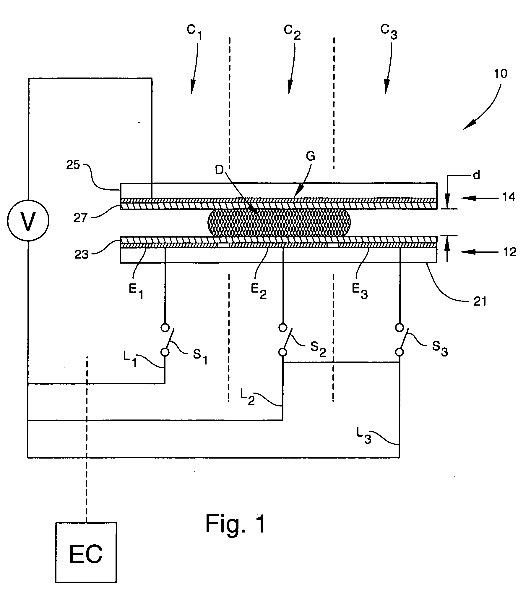
[0091] A prototype device consisting of a single linear array of seven interdigitated control electrodes E at a pitch of 1.5 mm was fabricated and tested. Control electrodes E were formed by patterning a 2000-Å thick layer of chrome on a glass lower plate 21 using standard microfabrication techniques. The chips were then coated with a 7000 Å layer of Parylene C followed by a layer 23 of approximately 2000 Å of TEFLON® AF 1600. Ground electrode G consisted of an upper plate 25 of glass coated with a conducting layer (R7027 of TEFLON® AF 1600 was also applied to ground electrode G. The thin TEFLON® coating on ground electrode G served to hydrophobize the surface, but was not presumed to be insulative. After coating with TEFLON®, both surfaces had a contact angle of 104° with water.

[0092] Water droplets (0.7-1.0 μl) of 100 mM KCl were dispensed onto the array using a pipette, and upper plate 25 was positioned to provide a gap d of 0.3 mm between the opposing electrodes E and G. A cust...


PUM

PropertyMeasurementUnit
sizeaaaaaaaaaa
sizeaaaaaaaaaa
contact angleaaaaaaaaaa

Abstract

Methods are provided for manipulating droplets. The methods include providing the droplet on a surface comprising an array of electrodes and a substantially co-planer array of reference elements, wherein the droplet is disposed on a first one of the electrodes, and the droplet at least partially overlaps a second one of the electrodes and an intervening one of the reference elements disposed between the first and second electrodes. The methods further include activating the first and second electrodes to spread at least a portion of the droplet across the second electrode and deactivating the first electrode to move the droplet from the first electrode to the second electrode.

Description

RELATED APPLICATIONS [0001] This application is a divisional of co-pending U.S. patent application Ser. No. 10 / 253,368 filed Sep. 24, 2002; the disclosure of which is incorporated herein by reference in its entirety.GOVERNMENT INTEREST [0002] This invention was made with Government support under Grant No. F30602-98-2-0140 awarded by the Defense Advanced Research Projects Agency. The Government has certain rights in the invention.TECHNICAL FIELD [0003] The present invention is generally related to the field of droplet-based liquid handling and processing, such as droplet-based sample preparation, mixing, and dilution on a microfluidic scale. More specifically, the present invention relates to the manipulation of droplets by electrowetting-based techniques. BACKGROUND ART [0004] Microfluidic systems are presently being explored for their potential to carry out certain processing techniques on capillary-sized continuous flows of liquid. In particular, there is currently great interest ...

Claims


Application Information

Patent Timeline
Patent Type & Authority Applications(United States)
IPC IPC(8): C07K1/26G01N27/447B01F11/00B01F13/00B01L3/00G01N1/00G01N1/10G01N15/06G01N21/00G01N35/00
CPCB01F11/0071B01L3/50273B01F13/0076B01F13/0084B01L3/502792B01L2300/089B01L2300/161B01L2400/0415B41J2002/14395G02B26/005B01L2400/0427C25B9/00B01L3/5027B01L2200/0605B01L2200/10B01F13/0071B01F31/65B01F33/3021B01F33/3031B01F33/30351G01N27/403B01L3/502784B01L3/00B01L2200/06B01L2300/165G01N27/44791
Inventor PAMULA, VAMSEE K.POLLACK, MICHAEL G.PAIK, PHILIP Y.REN, HONGFAIR, RICHARD B.
Owner DUKE UNIV
Why Eureka
Try Eureka