Optical film and its manufacturing method

a manufacturing method and optical film technology, applied in the field of optical films, can solve the problems of inorganic base increasing the cost, complicated process, method for producing conventional optical films, etc., and achieve the effects of low cost, excellent optical properties, and low cos

Inactive Publication Date: 2006-03-16
NITTO DENKO CORP
View PDF10 Cites 51 Cited by
  • Summary
  • Abstract
  • Description
  • Claims
  • Application Information

AI Technical Summary

Benefits of technology

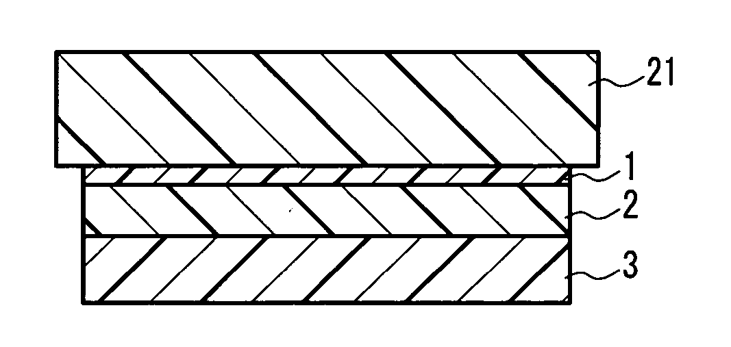
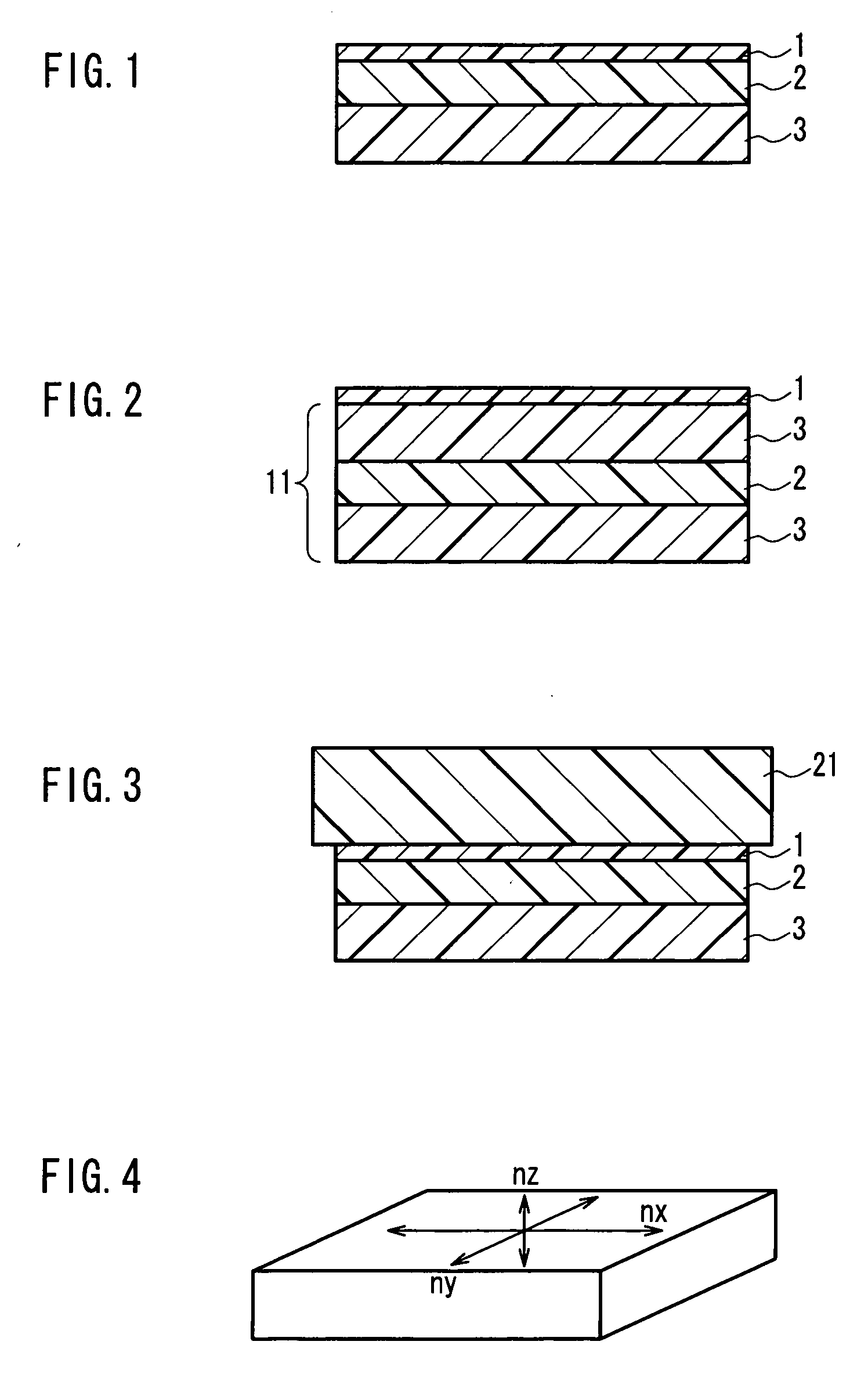
[0010] An optical film of the present invention is such that the birefringent layer is laminated on the transparent polymer film layer used as a base. Accordingly, the optical film can be used in a laminated state, thus it does not require operations for peeling the film off from a base or rolling the film. Moreover, the transparent polymer film layer is cost-effective. As a result, the optical film of the present invention c

Problems solved by technology

However, in a producing method that includes a stretching process, conditions regarding the stretching ratio and stretching direction or the like must be set in detail, which will require a precise control of the stretching and thus the processes will be complicated.
However, since the inorganic base itself cannot be used in a liquid

Method used


Image

  • Optical film and its manufacturing method
  • Optical film and its manufacturing method
  • Optical film and its manufacturing method

Examples


example 1

[0155] Polyimide, which was synthesized from 2,2-bis(3,4-dicarboxyphenyl) hexafluoropropane dianhydride and 2,2′-bis(trifluoromethyl)-4,4′-diaminobiphenyl, having a weight average molecular weight Ww) of 70,000 and a birefringence (Δn) of about 0.04, was dissolved in MIBK (methyl isobutyl ketone) so as to obtain a solution whose solid concentration was 15 wt %. A triacetylcellulose (TAC) film was stretched transversely 1.3 times its original length at 150° C. in a fixed-end transverse stretching so as to have a thickness of 75 μm, and the solution was applied onto the TAC film. This TAC film had a Δnd of 20 nm. By a subsequent heat treatment at 100° C. for 10 minutes, a solvent in the solution was evaporated and removed to form a layer, and at the same time, the TAC film was shrunk to shrink the layer, thereby obtaining a perfectly-transparent and flat optical film. The thus obtained birefringent layer had an optical property nx>ny>nz.

example 2

[0156] 75 weight parts of an alternating copolymer made of isobutene and N-methyl maleimide (containing 50 mol % of N-methyl maleimide) and 25 weight parts of an acrylonitrile-styrene copolymer containing 28 wt % of acrylonitrile were dissolved in methylene chloride so as to obtain a solution whose solid concentration was 15 wt %. This solution was cast on a polyethylene terephthalate (PET) film covering a glass sheet, kept at room temperature for 60 minutes and subsequently peeled off from the PET film, which was then dried at 100° C. for 10 minutes and later 140° C. for 10 minutes, and further at 160° C. for 30 minutes, thereby obtaining a transparent film. The film had an in-plane retardation (Δnd) of 4 nm and Rth of 4 nm.

[0157] The solution as in Example 1 was applied onto the thus obtained transparent film. By a subsequent heat treatment at 100° C. for 5 minutes, a layer was formed on the transparent film, and thus a perfectly-transparent and flat film was obtained. By a 10% l...

example 3

[0158] Polyimide, which was synthesized from 2,2-bis(3,4-dicarboxyphenyl) hexafluoropropane dianhydride and 2,2′-bis(trifluoromethyl)-4,4′-diaminobiphenyl, having a birefringence (Δn) of about 0.05, was dissolved in ethyl acetate so as to obtain a solution whose solid concentration was 20 wt %. This solution was applied onto the base as in Example 1. By a subsequent heat treatment at 130° C. for 5 minutes, a solvent in the solution was removed by evaporation so as to form a layer, and at the same time, the layer was shrunk to provide a perfectly-transparent and flat optical film. The birefringent layer of this optical film had an optical property nx>ny>nz.


PUM


Abstract

The present invention relates to an optical film that is excellent in optical properties and can be produced at low cost. In the optical film formed by laminating a transparent polymer film layer and a birefringent layer of a non-liquid crystalline polymer, the birefringent layer satisfies a condition represented by nx≧ny>nz and the in-plane retardation of the transparent polymer film layer is 50 nm or less. In the above formula, nx, ny and nz are the refraction indices in the X-, Y- and Z-axes directions of the birefringent layer, respectively. The X-axis direction is the axial direction in which the refraction index shows a maximum value in the in-plane direction of the birefringent layer, the Y-axis direction is the axial direction perpendicular to the X-axis direction in the plane, and the Z-axis direction is the thickness direction perpendicular to the X- and Y-axes directions.

Description

TECHNICAL FIELD [0001] The present invention relates to an optical film and a method for producing the same. BACKGROUND ART [0002] In liquid crystal displays, various optical films are used for improving the display performance. For example, an optical film (retardation film) that satisfies the condition (1) below is arranged between a liquid crystal cell and a polarizing plate, and used for compensating the viewing angle of a liquid crystal display. Such an optical film is produced by stretching a polymer film (see JP H03(1991)-33719 A, JP H03(1991)-24502 A, and JP H04(1992)-194820 A). nx≧ny>nz  (1) [0003] In the above formula (1), nx, ny and nz indicate respectively refractive indices in directions of an X-axis, a Y-axis, and a Z-axis in the optical film. The X-axis direction is a direction showing a maximum refractive index within the plane of the optical film, the Y-axis direction is a direction perpendicular to the X-axis direction within the plane, and the Z-axis direction ...

Claims


Application Information

Patent Timeline
IPC IPC(8): G02F1/1335G02B5/30
CPCG02F1/133528G02B5/3016G02B5/30G02F1/13363G02F1/1335
Inventor MURAKAMI, NAOYOSHIMI, HIROYUKINISHIKOUJI, YUUICHIHAYASHI, MASAKI
Owner NITTO DENKO CORP
Why Eureka
Try Eureka