
Process for producing high-strength spring

Active Publication Date: 2006-03-23
CHUO SPRING
View PDF1 Cites 17 Cited by
  • Summary
  • Abstract
  • Description
  • Claims
  • Application Information

AI Technical Summary

Benefits of technology

[0016] To improve the energy efficiency, it is preferable to perform the above-described process when the spring is cooled after a certain kind of heating process is performed on the spring. For a spring that needs a heating treatment (i.e. quenching and tempering), the aforementioned “heating process” means the final heating process (i.e. the tempering). For a spring that does not need such a heating treatment, the “heating process” means some other kind of heating process, an example of which is a removing-strain annealing performed after a cold-working process (e.g. coiling process). For a warm-formed spring, the temper heating is usually performed at a temperature within the range from 400 to 450° C. For a cold-formed spring, the removing-strain annealing that follows the coiling process is performed at a temperature within the range from 350 to 450° C. Therefore, the shot peening, prestressing and other necessary processes can be performed within the temperature range specified earlier. It is allowable to provide an additional heating step apart from the “heating process.” In this case, the shot peening and related processes may be performed while the heating operation is maintained, not in the course of a cooling process after the heating operation is stopped.
[0017] If the shot peening is performed in a warm environment where the spring still has a high temperature, the hardness of the spring (or work piece) relative to that of the shot particles becomes lower than that observed in the case where the shot peening is performed in a cold environment. Therefore, the shot peening produces a greater magnitude of plastic deformation on the surface of the spring, thereby generating a high level of compressive residual stress within the surface. It also makes the compressive residual stress to develop more deeply from the surface.
[0019] In the method according to the present invention, a rapid cooling process immediately follows the shot peening process performed at the above-specified temperature range. Therefore, the high compressive residual stress resulting from the warm shot peening is maintained until the spring reaches the room temperature. Thus, the spring manufactured by the method according to the present invention gains a higher level of durability.
[0020] The previous discussion also applies to the prestressing process. One object of performing the prestressing in a warm environment is to cause beforehand, in the course of the production, a plastic deformation (or sag) that can occur in the future while the spring is in service, and to immobilize beforehand any dislocations that may cause a plastic deformation. Performing a slow cooling process after the warm prestressing process allows the dislocations to move again while the temperature is high, which will cause the spring to sag in the future. In contrast, in the method according to the present invention, the rapid cooling process that immediately follows the warm prestressing process assuredly immobilizes the dislocations, so that only a minimal amount of sag is allowed to occur later while the spring is in service.
[0021] Furthermore, compared to the cold prestressing performed after the spring is cooled, the warm prestressing reduces the amount of compression of the spring necessary to create the same magnitude of permanent deformation. This effectively improves the evenness in the form (e.g. the free length and the bowing) of the spring observed after the prestressing.

Problems solved by technology

Such past techniques could not always meet the performance requirements for the latest springs that were put in service under much higher levels of working stress.

Method used


Image

  • Process for producing high-strength spring
  • Process for producing high-strength spring
  • Process for producing high-strength spring

Examples


Embodiment Construction

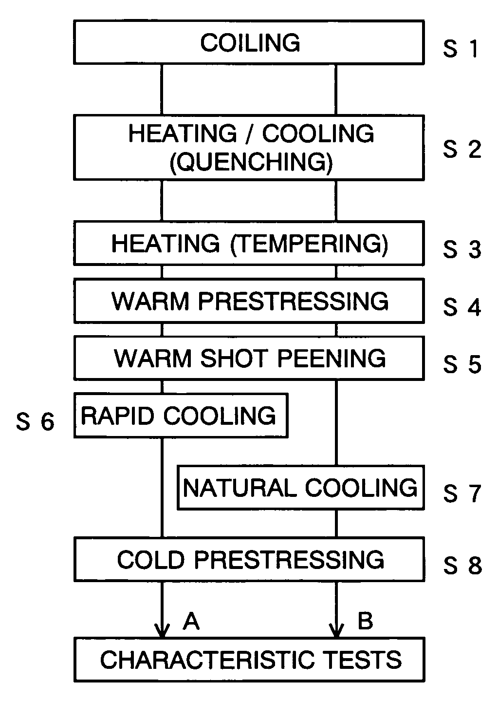
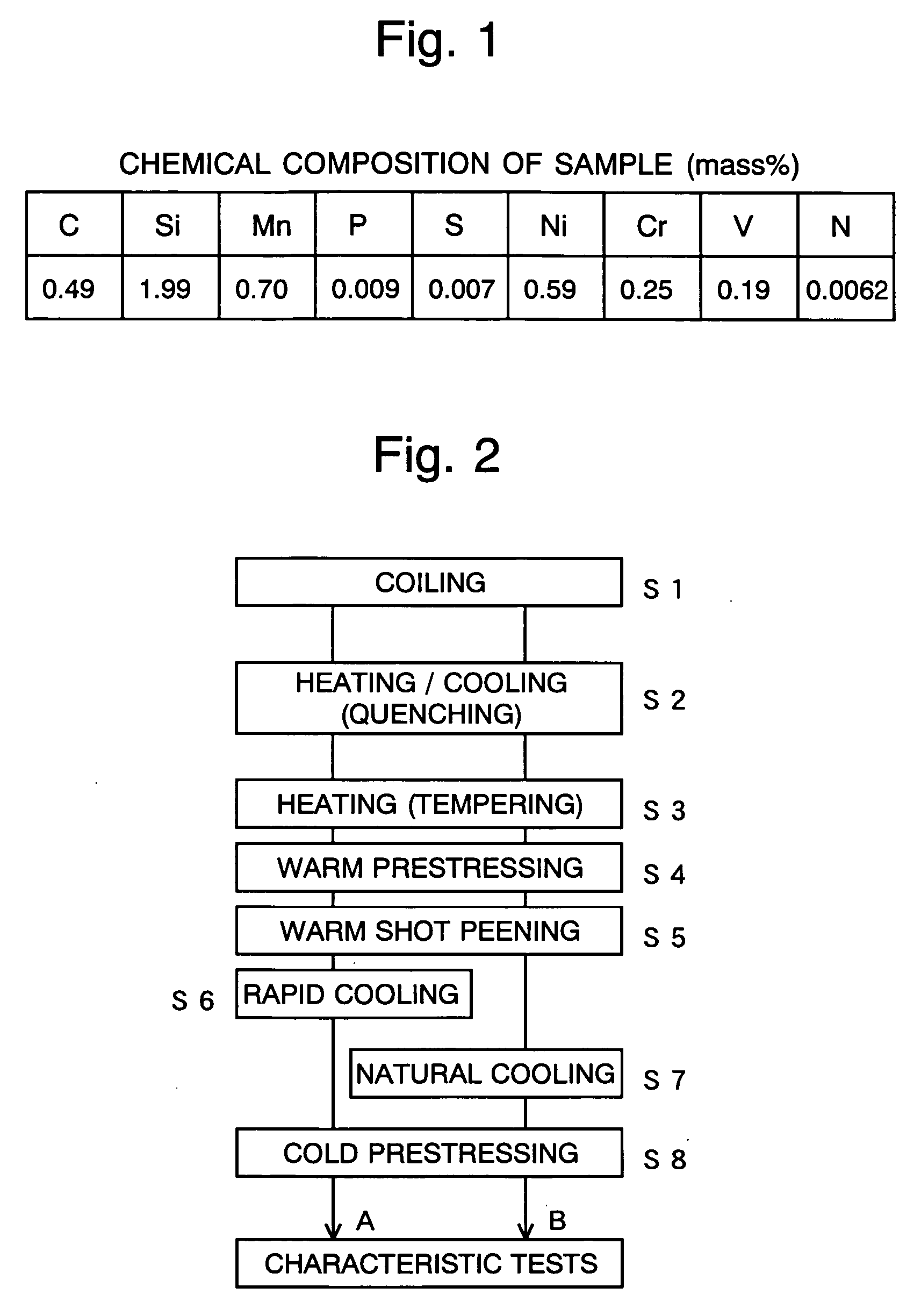
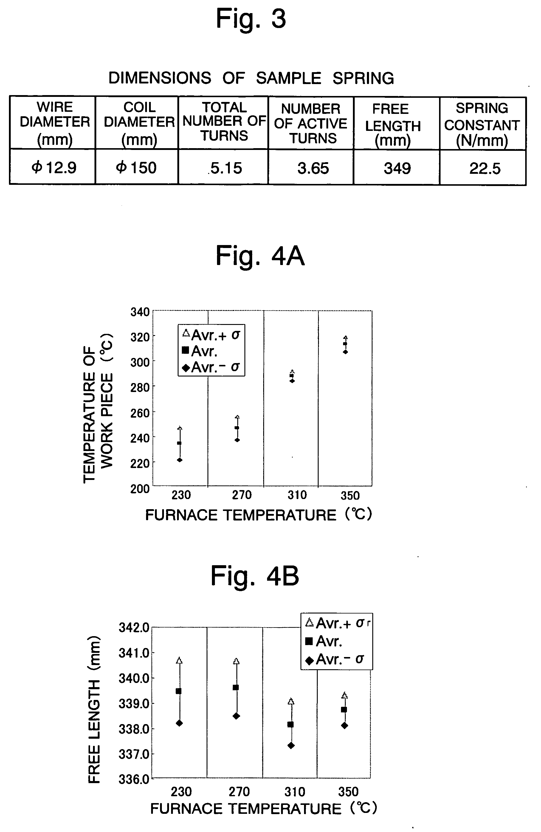
[0029] A test for confirming the effect of the method according to the present invention was conducted using a steel material having a chemical composition shown in FIG. 1. Several pieces of coil springs were manufactured by a process shown in FIG. 2. The dimensions of the coil springs are shown in FIG. 3.

[0030] As shown in FIG. 2, the test samples were divided into two groups (A) and (B). The sample springs belonging to group (A) were prestressed and shot-peened in a warm environment where the temperature of the springs was within the range from 265 to 340° C. Then, the springs were submerged under water for rapid cooling. In contrast, the springs of group (B) were naturally cooled (or air-cooled) after being prestressed and shot-peened in the same manner. The shot peening was performed under the following condition: arc height=0.37 mm, coverage=100%.

[0031] A tempering treatment for a spring includes the step of maintaining a quenched spring at a predetermined tempering temperatu...


PUM

PropertyMeasurementUnit
Temperatureaaaaaaaaaa
Fractionaaaaaaaaaa

Abstract

The present invention intends to provide a method for manufacturing a high-strength spring, which is capable of generating a higher level of compressive residual stress than that given by conventional methods. This object is achieved as follows: After the final heating process, such as the tempering (in the case of a heat-treated spring) or removing-strain annealing (in the case of a cold-formed spring), a shot peening process is performed on the spring while the surface temperature of the spring is within the range from 265 to 340° C. (preferably from 300 to 340° C.). Subsequently, the spring is rapidly cooled. Preferably, a prestressing process is performed before the shot peening process, or after the shot peening process and before the rapid cooling process. The rapid cooling process may be either a water-cooling process or an oil-cooling process. A forced-air cooling process may be used if the wire diameter of the spring is small.

Description

TECHNICAL FIELD [0001] The present invention relates to a shot peening method for manufacturing a spring, particularly a suspension spring, having a high level of durability (or fatigue resistance) and sag resistance. BACKGROUND ART [0002] As a method for remarkably improving the durability of a spring, shot peening is an indispensable process for a high-strength spring, especially for a suspension spring used in automobiles or a valve spring used in engines. [0003] In the shot peening process, a number of small particles are projected onto the surface of the target object. This process is apparently the same as the shot blast, a process that is performed to make the surface clean by removing burrs (or projections) resulting from cutting or forming work or scales (i.e. a hard oxide layer) resulting from a heat treatment. However, the two processes significantly differ from each other in respect to the strength and other conditions; for shot peening, the conditions are determined to ...

Claims


Application Information

Patent Timeline
IPC IPC(8): C21D9/02C21D7/06C21D8/00
CPCC21D7/06C21D8/00Y10S148/908Y10T29/479C21D9/02
Inventor NAKANO, TOMOHIROSAKAKIBARA, TAKAYUKIWAKITA, MASAMI
Owner CHUO SPRING
Learn More