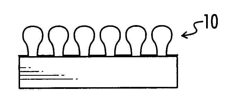
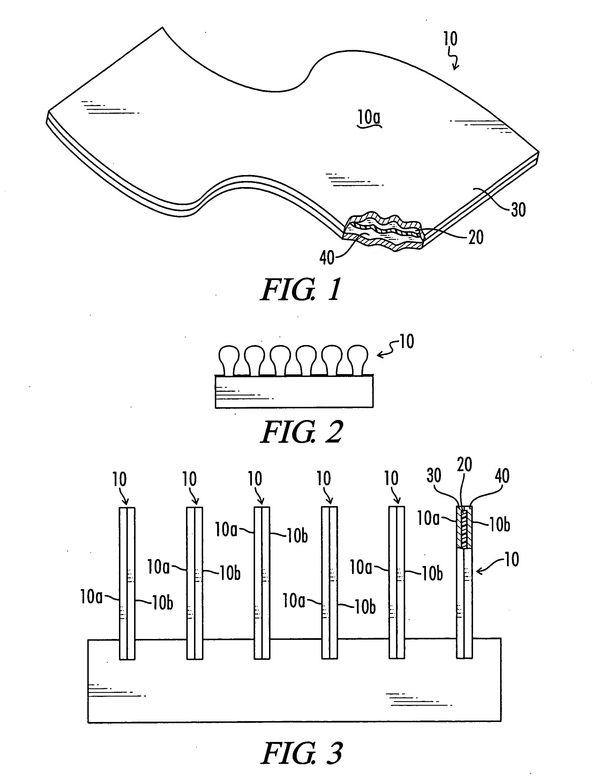
Sandwiched finstock

a technology of finstock and sandwiched finstock, which is applied in the direction of chemistry apparatus and processes, light and heating equipment, transportation and packaging, etc., can solve the problems of system failure, affecting the performance and reliability of the overall system, and affecting the performance of the individual components, so as to facilitate the dissipation of heat from a component and achieve high thermal anisotropic ratio

Inactive Publication Date: 2006-03-23
NEOGRAF SOLUTIONS LLC
View PDF15 Cites 27 Cited by
  • Summary
  • Abstract
  • Description
  • Claims
  • Application Information

AI Technical Summary

Benefits of technology

[0023] Accordingly, it is an object of the present invention to provide an improved thermal solution for facilitating the dissipation of heat from a component of an electronic device.
[0024] Still another object of the present invention is the provision of a thermal solution having a sufficiently high thermal anisotropic ratio to function effectively for heat dissipation from a heat collection article or material.
[0025] Yet another object of the present invention is the provision of a formable thermal solution which provides heat dissipation in an environment where available space is otherwise impractical.

Problems solved by technology

However, microprocessors, integrated circuits and other sophisticated electronic components typically operate efficiently only under a certain range of threshold temperatures.
The excessive heat generated during operation of these components can not only harm their own performance, but can also degrade the performance and reliability of the overall system and can even cause system failure.
The increasingly wide range of environmental conditions, including temperature extremes, in which electronic systems are expected to operate, exacerbates the negative effects of excessive heat.
However, the flexible nature of graphite materials makes it difficult to form complex structures or shapes with the graphite materials.
In addition, the attachment of graphite fins to metallic bases is also problematic, since graphite cannot be soldered into place in the same way metallic fins can.
Another issue with the use of graphite in electronic components is the fear, which may be unfounded, that individual graphite particles or flakes may flake off a graphite heat dissipation component.
Given the electrical conductivity of graphite, this would have the potential to interfere with the operation of the component in which the graphite material is located.

Method used


Image

  • Sandwiched finstock
  • Sandwiched finstock
  • Sandwiched finstock

Examples


Embodiment Construction

[0032] As noted, the inventive finstock article is a sandwich whose inner core is formed from sheets of compressed particles of exfoliated graphite, commonly known as flexible graphite. Graphite is a crystalline form of carbon comprising atoms covalently bonded in flat layered planes with weaker bonds between the planes. By treating particles of graphite, such as natural graphite flake, with an intercalant of, e.g. a solution of sulfuric and nitric acid, the crystal structure of the graphite reacts to form a compound of graphite and the intercalant. The treated particles of graphite are hereafter referred to as “particles of intercalated graphite.” Upon exposure to high temperature, the intercalant within the graphite decomposes and volatilizes, causing the particles of intercalated graphite to expand in dimension as much as about 80 or more times its original volume in an accordion-like fashion in the “c” direction, i.e. in the direction perpendicular to the crystalline planes of t...


PUM

PropertyMeasurementUnit
densityaaaaaaaaaa
temperaturesaaaaaaaaaa

Abstract

A finstock material for heat dissipation, which includes at least one sheet of flexible graphite sandwiched between two outer layers.

Description

[0001] Be it known that we, Daniel Witold Krassowski, a citizen of the United States of America residing at 13049 Heather Lane, Columbia Station, Ohio; Gary D. Shives, a citizen of the United States of America, residing at 2900 Elmer Drive, Brunswick, Ohio; Julian Norley, a citizen of the United States, residing at 17635 Plum Creek Trail, Chagrin Falls, Ohio 44023; and Robert Anderson Reynolds, III, a citizen of the United States of America, residing at 499 Oakmoor Road, Bay Village, Ohio, have invented a new and useful invention entitled “SANDWICHED FINSTOCK.”TECHNICAL FIELD [0002] The present invention relates to a sandwiched structure capable of being as a finstock in the manufacture of heat sinks and other thermal dissipation devices. By finstock is meant a material or article that can be utilized as, or to form, the fins used to dissipate heat. BACKGROUND OF THE INVENTION [0003] With the development of more and more sophisticated electronic devices, including those capable of i...

Claims


Application Information

Patent Timeline
Patent Type & Authority Applications(United States)
IPC IPC(8): B21D39/00
CPCH01L23/373H01L2924/0002Y10T428/12736Y10T428/12007Y10T428/30Y10T428/12535H01L2924/00B21D39/00F28F21/02B32B15/04B32B15/20B32B9/00
Inventor KRASSOWSKI, DANIEL WITOLDSHIVES, GARY D.NORLEY, JULIANREYNOLDS, ROBERT ANDERSON III
Owner NEOGRAF SOLUTIONS LLC
Why Eureka
Try Eureka